Xevelabs

To content | To menu | To search

Thursday, April 11 2013

USB2AX release

Hey lads!

After so many twist and turn of the road to release, the USB2AX is finally officially here, and available for all.

circle_pic.JPG

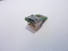
For thos who have not followed the 2 year development process (!), the USB2AX is a very small programmable USB interface that allows a computer to talk directly to Dynamixel servos, like the AX-12 or MX-xxT. I developed out of the need of such an interface to get Xachikoma to work.

Have a look at www.xevelabs.com for documentation and list of reputable distributors! Other distributors are coming soon, even in the US ;)

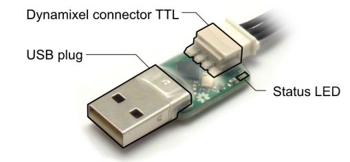
Main components: Dynamixel_parts_top.jpg

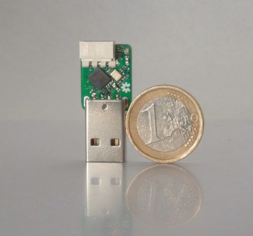
Size comparison: usb2axv31_front_euro_s.JPG

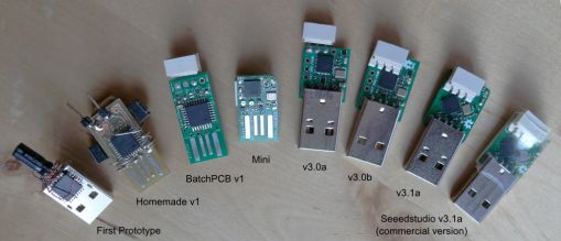
The whole familly picture: USB2AX_Family_named.jpg

Saturday, March 16 2013

PhantomX Reactor Arm (Part 2)

First, a little feedback on the problems I had in Part 1, thanks to Tyberius of Trossen Robotics:

  • Hex keys: already solved! Newer kits have good ones in a reasonable number :)
  • Charred ABS: already solved! Newer kits will be made with Plexiglas-G, no more burnt black powder.
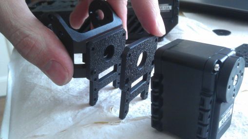
  • Hubs: that's how they are nowadays when Robotis makes them :( I noticed the fault doesn't lie only on the hub (BTW, chubbiness is normal for these parts it seems), the brackets are at fault too, since the same hub can move freely in one bracket and not in another one. Possible solution: use a little file and adjust very slightly the hole in the bracket.
  • Localized power cords: not gonna happen, it's understandably a logistical nightmare, and beside it's not that hard to replace just the offending cord or to have a $1 plug adapter.

As I'm going to move quite a lot in the next few days, I started assembling the rest of the arm before the base, with the goal of doing as much as possible without making the arm too big to be transported.

Upper Arm section:

Step 1: mount the thick plate rough side down. Be careful when inserting the screws not to remove the nuts... My advice: put a finger on the nut while you put the screw, then screw it at least half a turn before inserting the next, and at last tighten everything.

Step 4: if you get THAT, then you did it WRONG. 2013-03-15_15.44.21.jpg The screw goes through the plate, then in the 15mm standoff, and the 10mm F-F goes on the 15mm one.

Wrist:

Now it's getting technical. You have lots of alternatives (bracket F1 or F2, wrist rotation or not). I'll go with F2 and wrist rotation. All the pics in the manual are for F1. Since F2 is not symmetrical, put the over-hanging part of the Bottom Back Bracket on the opposite side of the bend of the F2 bracket, like that:
2013-03-15_16.00.44.jpg

Wrist rotation servo:

Step 1: "Next mount the Top and Bottom Back Brackets to the back of Servo #7." The pic is not very helpful here: it means stacking the top Reverse Bracket on the Bottom Reverse bracket, and then putting the servo on top of that, like that.
2013-03-15_16.09.12.jpg
Actually, the picture two step later explains it well too. I put the rough facing the same direction, contrary to what the pics show, but it's not an important point.

All smooth up to the wiring step, that requires a tool to push the plug all to it's correct position. Now back to the gripper!

Gripper Assembly:

Ha! From the list of required tools, that's where the 2mm hex starts getting useful! My apologies four doubting you! .. Except there is no screw of this size in sight. :/ A relic of the past maybe. For some reason I got 4 gripper arms. In fact, I have double the number of each of the small parts (bushings, screws...) but the right number of big parts. It seems to be normal, and I like to have extra of the breakable and losable pieces :)

Step 1: 8mm screws... yeah, they are a little long and will scratch the side of the case, but that's nothing to be alarmed about. Step 2: building the washer assembly is a lot less fun. First try resulted in a crushed bushing as soon as I applied enough force to make it possible to drive the screw... Hopefully I had a lot of spare. Using a pair of pliers with little teeth helps a lot, and loosening the hole a little with the hex key (or best, a small drill - 1.7mm maybe? - if you have one). One modification to the washers that would make this operation a breeze would be to have a square flange => you could put the screw without having to apply pressure to the bushing itself, making this operation much easier and much less prone to damage the washer.

INTERLUDE: Here I took the train for the first part of the trip. The arm, unfinished, has been put unceremoniously in my luggage between my socks and t-shirts.

One of the things I find a little annoying in terms of design with this kit is that to access any interface between two assemblies, you have to disassemble nearly everything in reverse order up to that point. Let's say I want to change the hubs between the base and the runners: I have to separate the runners, which requires removing the plates between them, and also to disassemble the base to access the screws used to fasten the F1 brackets on servo 2 and 3. There is of course no way to check the tightening of all the screws quickly. And if for example you have one of the first nuts you put in this F1 bracket that decides it prefers its freedom while you are trying to carefully put a screw through it, then you are a sad panda >_>. It's exactly the same with the way the base is built: you can't for example remove it quickly to be able to fit the arm in your luggage. Modularity would be greatly appreciated.

Also, look at the servo #1. It is supposed to be coaxial with the giant ball bearing, but there is no play in the assembly to recover from any alignment errors that are made possible by the tolerances in the size of the holes of the various screws. The bearing itself has (as is expected of it) very little axial play. I chose to loosen the 4 screws between servo #1 and the pan plate, and I will try to re-tighten them once everything is in place, since they are nearly accessible even when the arm is fully assembled.

I chose not to use the Pan Cover, this way when the arm is folded it can rest on the outer ring of the ball bearing regardless of the arm orientation. Just a personal preference.

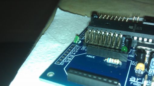
Mounting the Arbotix: I noticed one of the LED is broken.
2013-03-12_22.27.32.jpg
No trace of the missing part in the package, it happened before that. I'll change it somewhere down the line, not a big deal.

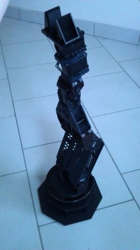
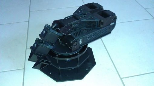
Yeah, all assembled! It looks awesome :) It's going to need its own bag next time I take the train ^^
2013-03-16_17.06.07.jpg
2013-03-16_17.06.27.jpg

I have a LOT of leftover screws and nuts (for some I did not need even use half of what I had), as well as two F3 brackets that are never used in the assembly guide. I guess that's another little oddity that the normal kits don't have.
2013-03-16_17.40.27.jpg

Next time, power-up and making it move, from even another city :) Yeah!

Tuesday, March 12 2013

PhantomX Reactor Arm (Part 1)

In the beginning of January, I won a contest at Trossen Robotics. Thanks guys :3
The idea of the contest was to show off your robot, talk about it, and the most interesting mix of robot and documentation would get a prize. I entered with Xachikoma, and won the Trossen Robotics PhantomX Reactor Arm this way. It took some time to get there due to a shortage of AX-12A, and I finally got an evening to start playing with it. Here is the account of my first encounter with this great robot kit designed by passionate robot makers :)

''Excuse the quality of the photos, my regular camera has been stolen when I left it in my luggage in a cloak room at the train station in Kolkata (at least my laptop and the robot, which were in the same luggage, were still there...). ''

The expected result: phantomxdeluxearm-assembly-final.jpg
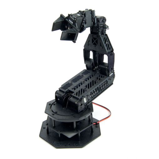
Opening the box

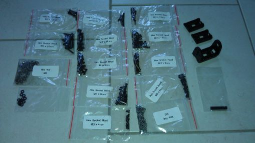
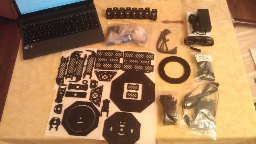
When you open the box, you are greeted by a lot of plastic bags, one of witch clearly shows 8 AX-12A servos. That's for the model with wrist rotation, otherwise you only have 7. The other bags contain laser-cut plastic parts, electronics (Arbotix + FTDI cable + everything to power it), Dynamixel cables (with black plugs!), parts for the Gripper, and the nuts, bolts, screw-drivers, thread-lock and miscellaneous stuff.

This kit is very complete, you won't need any unusual tool :)

As soon as you open the biggest bag, you are greeted with the typical burnt plastic smell that comes with laser-cutting.
First warning: the laser cut parts may still have some black residue, so prepare something to wipe them, or even better, clean them up with sponge, water and soap (ONLY THE LASER-CUT PLASTIC PARTS, don't go cleaning the giant ball-baring nor the Parallel gripper).
2013-03-12_21.34.20.jpg

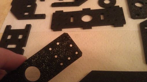
Now that the plastic parts are clean(er), you might notice some of the thicker parts have un-detached pieces in the holes for the screws. If so, remove them.

Here, one hole is still obstructed: 2013-03-12_21.36.47.jpg
Assembly

Let's go to the product page and from there look at the assembly manual.

Tools needed: it seems that I will only need pliers and a flat-head screwdriver. Ok, let's check the included tools... Strange, there's a lot more of them than I thought! And indeed, it might be an error on my kit, because there are a total of 3 hex keys of 1.5mm for M2 screws (two with a handle, a black one without), 3 hex keys of 2.5mm for M3 screws (one with a handle, a black one, a gray one), and what looks like a gray 2mm hex key, that doesn't go with any of the screws we have here.
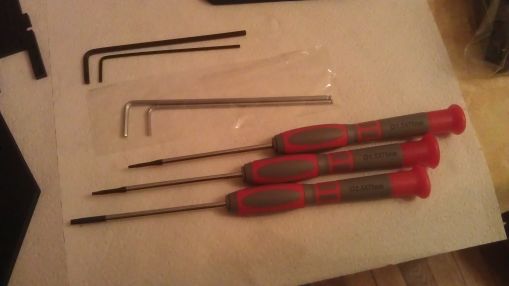
2013-03-12_22.04.04.jpg

Parts: it's always a good idea to check the presence of every and each part before starting to assemble. The "reverse brackets" were in the Gripper bag, I missed them at first.
All there, let's go!

Step 1: all OK.

Step 2: the two 1.5mm hex drivers died before I finished the first screw >_< GUYS! That's not OK!
Fortunately the hex key fared better and could finish all my M2 screws. The M3 hex driver worked OK, but... but... that's the AX hub assembly that doesn't behave as it should this time! It is had to insert, and then doesn't turn freely like the regular ones from Robotis, and when you move the F2 bracket back and forth, it resists and ends up unscrewing the M3x10 >_<

Here is the noise it makes when the M3 screw is properly tightened:

AX hub and frame noise

I don't have access to my regular tools so I can't measure which part is not to specs, but that's a problem. Looking at the parts, I would say it's the hub assembly that is a little "puffy". Out of the five pieces in the kit, only one works as it should... :/
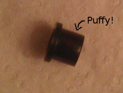
puffy_hub.jpg

I'm going to mount everything anyway, and before turning it on I'll replace them with original ones from Robotis. No use looking good with black components if it does not work.

A good habit to take right now if you don't have it yet: tighten your screws properly! Thread-lock is great, but it doesn't make a proper tightening obsolete. When you have multiple screws between two parts like that, tighten every one of them loosely first, then do a second pass to finish them.

Step 3: nothing special, same as before for the hubs.

Step 4: assemble the runners of each arm. 60 bolts total... I'm sure it could be done with less than that - it would not look as cool, but darn would it save my wrist from aching ;)
7 The shape of the parts avoids assembly errors: as long as you keep the rough side outside, there's only way to fit the servos. You just have to be careful about the numbers of the servos (you can't see them anymore once the servo is mounted), and the orientation of the F4 brackets.
If you tighten really too much, you're going to have a hard time at step 8, be careful.

Step 5: Cable routing, nothing special. I love the black Molex plugs :)

Step 6/7 (which is more like one step with two pictures): I'm beginning to regret that the steps are not numbered, or that there isn't a reminder of what the F-F standoff looks like or which plate is the bottom one. Guys, think IKEA-style instructions, where you don't have references to other pages anywhere! Other solution to the problem: having a second tab with the instruction, this time opened at the part list section.

Step 8: Assemble the two arms and the two plates to get your whole main section of the arm. The assembly is extremely rigid and that's awesome, the only thing I dislike about it is that I will have to remove a lot of stuff to change the hubs...

Before puting the top plate: 2013-03-13_00.20.55.jpg
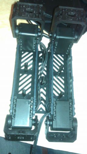
End of part 1, I'm going to sleep.
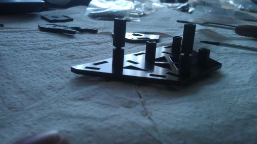
Thursday, January 31 2013

There and back again

(this post has been written long ago and I kept the original date even though it is published on 2013/03/12)

Techfest has been a very nice experience, with a lot of wonderful encounters :)

I haven't even had time to unpack that I got invited to present Xachi to another great Indian technology festival, Kshitij 2013! This event, dubbed a techno-managment fest, will be held from Feb 1 to 4, at IIT Kharagpur, around a hundred kilometers west of Kolkata.
In fact I am writing from one of the comfy armchairs in Dubai airport where I have a connection. I got to fly on an A380 to get there \o/

See you there :)

Tuesday, January 1 2013

Happy new year from India

2013 started for me with a nice chat with fellow Techfest exhibitors, looking by the window of our hotel at the fireworks spawning everywhere in the city of Mumbai. A nice way to start a year :)

Yesterday, with my coordinator Jaydeep, we went to visit the south part of Mumbai (a little more than 1h to go, more than 2 hours to get back with the traffic!), and Elephanta Island, where unfortunately the caves were closed :( Still it was a nice occasion to get away from the smog of the city, hike a little and breath some fresh air. Ho, and see monkeys too!

Techfest starts in 2 days, and I still have some work to do on the robot, as well as some sights to see (today, we're going to have a look at the Kanheri caves in Sanjay Gandhi National Park). Stay tuned ;)

Sunday, December 23 2012

Packing up for Techfest

Xachikoma will be present in Techfest, 3-5th January 2013 in Mumbai, India!

It will demonstrate some of its abilities to the crowd in the International Exhibits section ;) Come say hello!

Saturday, November 10 2012

Deadbugging fine pitch BGA

When you don't have a breakout board to test that fancy new BGA chip you just received, you make do with what you have at hand.

After seeing a few posts about "deadbugging" (soldering wires to the leads or pads of a component instead of soldering it on its recommended footprint) of BGA chips on Dangerous Prototypes, some with "big" solder balls, and some with smaller ones, I thought I would share my latest attempt at it.

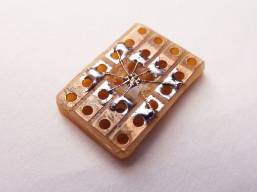
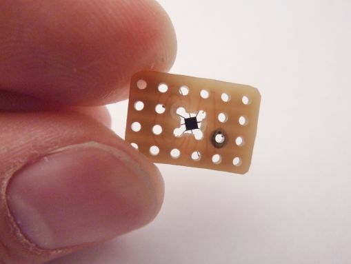
tmp006_deadbug_01.JPG tmp006_deadbug_02.JPG

The chip is the TMP006 from TI, a great little temperature sensor / infrared thermopile which, when properly soldered and calibrated, gives both the local temperature and the temperature of whatever is in front of it. The chip in itself might be inexpensive, I could not find a reasonably priced ready-to-buy breakout board. Dangerous Prototypes has a PCB, and TI sells a big and expensive evaluation module, and that's it.

The TMP006 is a 1.5mmx1.5mm component with 0.5mm pitch BGA featuring 8 connections. As the sensor in itself needs a line of sight with what you try to measure the temperature of, I started by making a hole in a piece of stripboard, then cutting andtinning the strips to get 8 pads all around the hole.
Then, one by one, with 36awg wire I connected the pads...

Deadbug soldering

And Voila :)
Notice the solder balls are lead-free and sometimes have a hard time melting with my overly-oxidized budget iron... :/
I had to re-solder two of them for which the solder ball did not melt enough the first time.

It's not necessarily the prettiest, but it worked well enough: I could get valid local temperature data, yet remote temperature was jumping all over. A quick look around the web and it seems that it is not unheard of for this sensor to report garbage when you don't follow the particularly specific footprint and assembly process.

Since the most pressing matter was to develop the low level driver, It was not completely in vain. Yet, I'll have to wait for the next prototype with the sensor properly soldered on the project board to finish the higher level code (calibration and computation of the remote temperature).

Do you want to know more ? Here is an excellent video from Dave of EEVBlog if you want more information on this technique : http://www.youtube.com/watch?v=q53u...

EDIT: After some time of use, it appears very clearly that this technique is NOT durable. The connections tend to break fairly easily. Better keep this technique for the times when there is NO alternative, and try to do it the right way (reflow soldering on an adequate PCB) otherwise.

Wednesday, April 4 2012

USB2AX mini

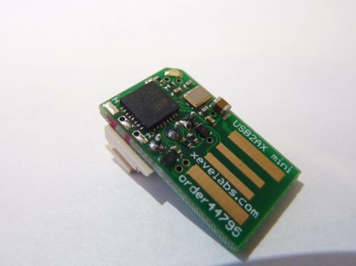
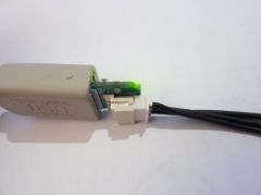
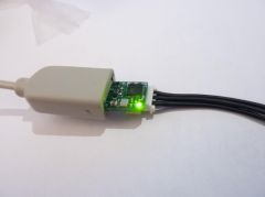
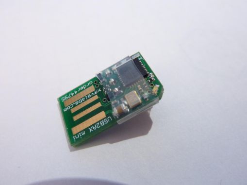
The USB2AX project is still on track (more on that in a next post). As a little side-project, I wanted to have a try at making the USB2AX even smaller while retaining all the current characteristics (ATmega32u2, ESD protection, LED, etc). That's how the USB2AX Mini came to be.

USB2AX_Mini___12_.jpg

The motivation is just to have fun and satisfy my lust for optimization. Or some might say pseudo-optimization here since by over-optimizing size, some other aspects of the device suffer, like quality of the physical connection (resistance to vibrations and yanking). But hey, this one will most probably never go beyond the prototyping stage, so please leave it to that.

I wanted to stay away from some obvious ways to make it smaller, like putting components on both side, using components too-small-to-be-soldered-with-my-crappy-prototyping-tools, requiring custom mechanical parts (like the ones used in the miniature bluetooth or WiFi dongles, with the electronics inside the USB plug) or cutting functionalities (ESD protection, status LED...). Thus it had to be possible to assemble with the same tools I already use and keep the nearly the same BOM as the v3.0. Working on the connectors seemed like the way to go, as they occupy around 75% of the board real estate.

The ideas here are:

  • use a PCB USB connector, with gold fingers this time (saves 10mm)
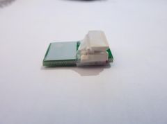
  • move the dynamixel connector so it is the closest possible to the USB plug, on the other side of the electronic components (saves around 5mm)
  • route the USB lines between the Dynamixel connector's pads (saves still a little bit more)

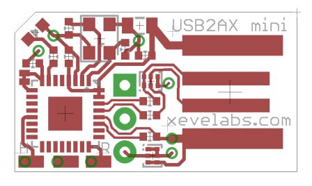
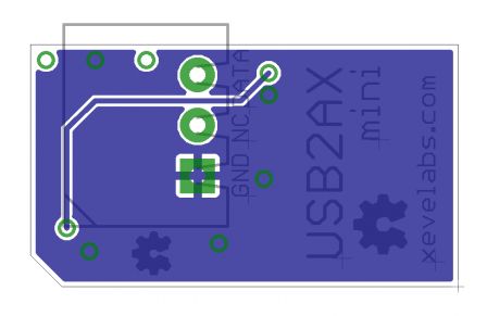
And that's the result:
usb2ax_mini_top.png
usb2ax_mini_bot_mirror_.png

With a total length of around 22mm (compared to the 37mm of the V3.0), it already looks a lot smaller. However, by moving the Dynamixel connector a few millimeters inside the PCB, the actual length when measuring the device with a Dynamixel cable plugged in is 17mm shorter (41mm for the v3.0)!

From an electronics standpoint, it's nearly identical to the USB2AX v3.0. The only thing that changed is that instead of protecting each line of the serial port with a 47ohm and the anti-ESD chip, and then connecting them, I connected them directly then protected the remaining DATA line.

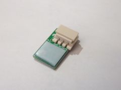
USB2AX_Mini___15_.jpg USB2AX_Mini___11_.jpg

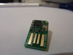
The PCB USB plug has, as expected, some disadvantages. Without modification, you have poor or non-existent electrical contact, that can be fixed by increasing the plug thickness with a piece of tape (here, I use 0.5mm thick Teflon tape). I could have had the PCB made with 2mm thick material, but it costs a lot more with Seeedstudio Fusion. The problems I used to have (see v1.0) with the electrical contact quality have been fixed by getting the board gold-plated (ENIG), with additional gold fingers on the contact pads.

USB2AX_Mini___20_.jpg USB2AX_Mini___19_.jpg
It feels like you are plugging the Dynamixel cable directly into the USB port :P

USB2AX_Mini___21_.jpg USB2AX_Mini___22_.jpg USB2AX_Mini___24_.jpg

I tried to protect the board with some heat-shrink tubing, but it tends to slip when shrinking, I had to do it 3 times to get this result.

All in all, I think it's a fairly cool little board, and it still does its job, so I'm happy with it :) As always, code and files are available in the Git repository :)

Friday, January 6 2012

Hackerspace in Nancy

I'm now officially a member of the one and only NYBI.CC! (page on hackerspaces.org : http://hackerspaces.org/wiki/NYBI.C...)

Nybicc_square_180px.jpg

NYBI.CC, or NancY BIdouille Création Construction (roughly translates to tinkering, creating and "making stuff" (club) of Nancy ) is a young makerspace/hackerspace with already a lot of very cool people, working on projects as diverse as RepRaps, Remote Underwater Vehicles, FPGAs, NeufBox hacking, blinky stuff, mini laser engravers, educational projects of all forms, ...

I've been coming to the weekly meeting on and off for a few month now (basically since all the ground work on the place itself is done : staircase, walls, lighting,... :P )

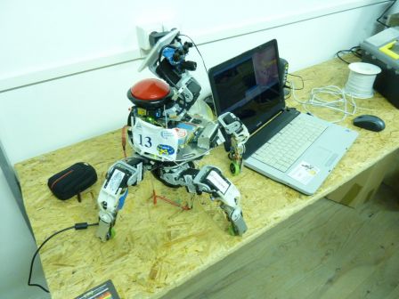
And on Wednesday, I also showed Xachikoma to the other members :) mP1010264_1365x1024.jpg
mP1010265_1365x1024.jpg

Meanwhile, a reprap was beening fixed... It's a nice little Huxley that suffered some damage, and they had, among other things, to straighten some PLA parts using a SMD rework station :D
Fun times ^^ mP1010266_1365x1024.jpg

Friday, December 30 2011

December tales

December has been a cool month, and I'm not only speaking of the weather.

TechTic&Co

logo-tech-tic-co.png

TechTic&Co is an association created to promote science and robotics in Lorraine (the region I live in) and in the northeast of France. The reach is quite wide: the general public, but also students, professionals, researchers, ... everybody who could take part in the "robolution" (robotics revolution) Bruno Bonnell, CEO of Robopolis, talks about.

Their first big public event is a one week long exhibition (FR) covering various aspects of robotics, and it will take place in Oct. 2013 in Metz, FR.

Have a look at their website (FR): http://www.techtic-co.eu/

Preparing such a big event requires a lot of work and a lot of collaboration with public services, other associations, industrials, high schools, etc. So after a few month of the staff tirelessly contacting potential partners, the date of Dec. 8th had been chosen to gather all these people in one place to make sure everybody is on the same page.

For this occasion, I have been asked to be the guest of honor, and to bring Xachi for a little demo. I don't have pictures/videos, but imagine me, awkward as ever, trying to explain my crazy passion to a crowd of 120 influent people (politicians, entrepreneurs, press)... Fun times ;)

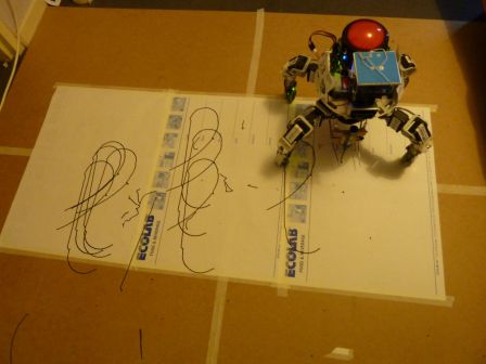
Xachi learns to write

A week after the inaugural meeting of TechTic&Co, Xachi was once again up to make the show. This time, it was for a ceremony to celebrate the anniversary of the University the school I graduated from (ESIAL) depends of.

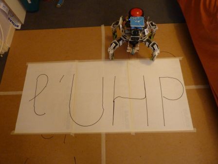
The name of said university is "Université Henri Poincaré" (aka UHP), after the great French mathematician born in the same town the university resides in. So the plan was to have an interlude near the end of the ceremony, where a student-made robot would write on a giant piece of paper "Merci l'UHP" ("Thanks to UHP"). I'm not a student any longer, but my robot was functional, cool and available, so in the end I got to do it.

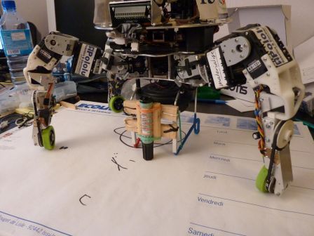
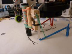
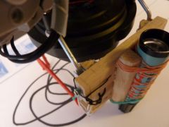
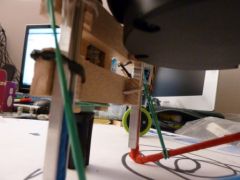
To write stuff, I made an add-on to mount a pen on the robot. It's a little slide that can move up and down the support structure beneath Xachi's body. The pen is clamped on the slide with rubber bands, and pressure of the pen on the paper is maintained thanks to two other rubber bands driving the slide downward.

mP1010246_1365x1024.jpg
mP1010250_1365x1024.jpg mP1010248_1365x1024.jpg mP1010249_1365x1024.jpg
The slide with the pen on it

mP1010252_1365x1024.jpg
Working on the cursive L

As time was scarce, I had to do some quick and dirty coding to get things done in less than 24h... So the letters were divided into a few segments and curves each, and I tried to make them look like letters by tweaking the motion parameters (speed vector, turn rate and duration). In the end, since programming "Merci" would have taken too much time, I only taught the robot to write "l'UHP", and "Merci" was written beforehand on the piece of paper, by hand.

Have a look at the last test before leaving for the event venue:

Xachi writes stuff...

mP1010254_1365x1024.jpg
Xachi is proud of his calligraphy.

This is completely scripted, but making an automatic path generator taking a set of lines as input seems like a fun project for later...

I should get the videos of the event at some point in the future, stay tuned.

- page 2 of 8 -