PhantomX Reactor Arm (Part 1)
By Xevel on Tuesday, March 12 2013, 21:49 - Permalink
In the beginning of January, I won a contest at Trossen Robotics. Thanks guys :3
The idea of the contest was to show off your robot, talk about it, and the most interesting mix of robot and documentation would get a prize. I entered with Xachikoma, and won the Trossen Robotics PhantomX Reactor Arm this way. It took some time to get there due to a shortage of AX-12A, and I finally got an evening to start playing with it. Here is the account of my first encounter with this great robot kit designed by passionate robot makers :)
''Excuse the quality of the photos, my regular camera has been stolen when I left it in my luggage in a cloak room at the train station in Kolkata (at least my laptop and the robot, which were in the same luggage, were still there...). ''
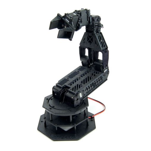
The expected result:
Opening the box
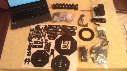
When you open the box, you are greeted by a lot of plastic bags, one of witch clearly shows 8 AX-12A servos. That's for the model with wrist rotation, otherwise you only have 7. The other bags contain laser-cut plastic parts, electronics (Arbotix + FTDI cable + everything to power it), Dynamixel cables (with black plugs!), parts for the Gripper, and the nuts, bolts, screw-drivers, thread-lock and miscellaneous stuff.
This kit is very complete, you won't need any unusual tool :)
As soon as you open the biggest bag, you are greeted with the typical burnt plastic smell that comes with laser-cutting.
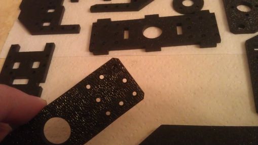
First warning: the laser cut parts may still have some black residue, so prepare something to wipe them, or even better, clean them up with sponge, water and soap (ONLY THE LASER-CUT PLASTIC PARTS, don't go cleaning the giant ball-baring nor the Parallel gripper).
Now that the plastic parts are clean(er), you might notice some of the thicker parts have un-detached pieces in the holes for the screws. If so, remove them.
Here, one hole is still obstructed:
Assembly
Let's go to the product page and from there look at the assembly manual.
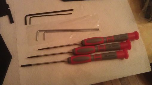
Tools needed: it seems that I will only need pliers and a flat-head screwdriver. Ok, let's check the included tools... Strange, there's a lot more of them than I thought! And indeed, it might be an error on my kit, because there are a total of 3 hex keys of 1.5mm for M2 screws (two with a handle, a black one without), 3 hex keys of 2.5mm for M3 screws (one with a handle, a black one, a gray one), and what looks like a gray 2mm hex key, that doesn't go with any of the screws we have here.
Parts: it's always a good idea to check the presence of every and each part before starting to assemble. The "reverse brackets" were in the Gripper bag, I missed them at first.
All there, let's go!
Step 1: all OK.
Step 2: the two 1.5mm hex drivers died before I finished the first screw >_< GUYS! That's not OK!
Fortunately the hex key fared better and could finish all my M2 screws. The M3 hex driver worked OK, but... but... that's the AX hub assembly that doesn't behave as it should this time! It is had to insert, and then doesn't turn freely like the regular ones from Robotis, and when you move the F2 bracket back and forth, it resists and ends up unscrewing the M3x10 >_<
Here is the noise it makes when the M3 screw is properly tightened:
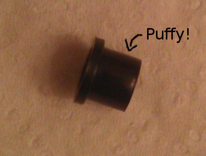
I don't have access to my regular tools so I can't measure which part is not to specs, but that's a problem. Looking at the parts, I would say it's the hub assembly that is a little "puffy". Out of the five pieces in the kit, only one works as it should... :/
I'm going to mount everything anyway, and before turning it on I'll replace them with original ones from Robotis. No use looking good with black components if it does not work.
A good habit to take right now if you don't have it yet: tighten your screws properly! Thread-lock is great, but it doesn't make a proper tightening obsolete. When you have multiple screws between two parts like that, tighten every one of them loosely first, then do a second pass to finish them.
Step 3: nothing special, same as before for the hubs.
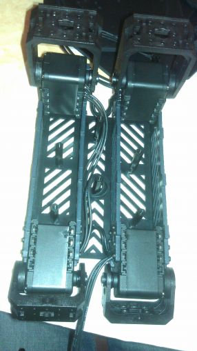
Step 4: assemble the runners of each arm. 60 bolts total... I'm sure it could be done with less than that - it would not look as cool, but darn would it save my wrist from aching ;)
7
The shape of the parts avoids assembly errors: as long as you keep the rough side outside, there's only way to fit the servos. You just have to be careful about the numbers of the servos (you can't see them anymore once the servo is mounted), and the orientation of the F4 brackets.
If you tighten really too much, you're going to have a hard time at step 8, be careful.
Step 5: Cable routing, nothing special. I love the black Molex plugs :)
Step 6/7 (which is more like one step with two pictures): I'm beginning to regret that the steps are not numbered, or that there isn't a reminder of what the F-F standoff looks like or which plate is the bottom one. Guys, think IKEA-style instructions, where you don't have references to other pages anywhere! Other solution to the problem: having a second tab with the instruction, this time opened at the part list section.
Step 8: Assemble the two arms and the two plates to get your whole main section of the arm. The assembly is extremely rigid and that's awesome, the only thing I dislike about it is that I will have to remove a lot of stuff to change the hubs...
End of part 1, I'm going to sleep.
