Xevelabs

To content | To menu | To search

Tuesday, April 5 2011

Nearly final sillouette

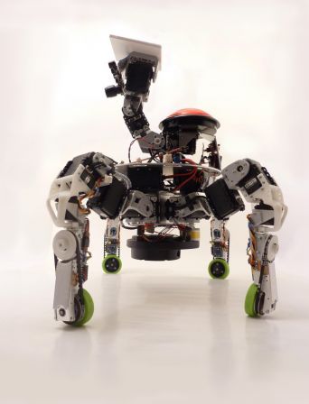
A lot happened since last post, and things are getting very close to their final shape.

Xachikoma_20110404_1.jpg

Xachikoma_20110404_2.jpg

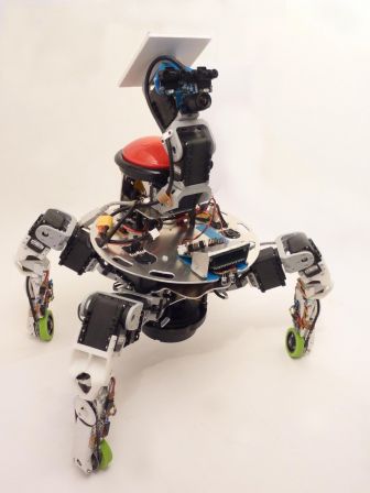
The robot got some brand new 3D printed motor mount (thanks i.materialise!), all the required electronics in the legs, a second camera and a rotating laser distance sensor (the Neato LDS, from the XV-11 vacuum cleaner robot)!

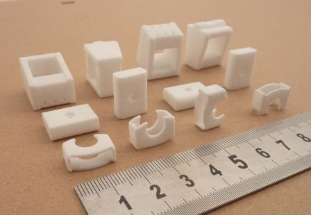
New 3D printed parts

From front to back row: a part used to lock the ball bearing in place, the lower bearing mount and the motor mount, motor_mounts.jpg
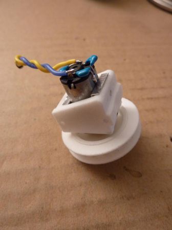
That's what the motor + motor mount + pulley looks like when everything is assembled. This goes inside the aluminum tube. The motor is taken between two layers of 0.25mm aluminum sheet. With this, there is no risk of deformation of the polyamide part, plus it allows for two M2 grub screws (both in the bottom of the part, one close to the front, one close to the back) to secure the motor and reductor in place without blocking the gears. motor_mounted.jpg
The motor mount and the part with the ball bearing are now two distinct elements. With the new motor mount design, it was necessary to split the two, as one is fixed and the other has to be adjusted to have the right belt tension. support_bearing.jpg
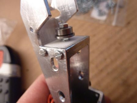
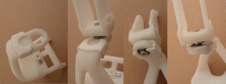
My first thoughts when I designed the mechanism was that little to no effort would apply to move the bearing out of its hole, but torsion in the tibia support part quickly showed that it was not the case. This little part keeps the bearing where it is. Here it's demonstrated with an old motor mount. bearing_lock.jpg
Leg Control Board

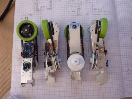
Each leg is fitted with a Baby Orangutan B-328 that controls the motor, the magnetic encoder, the wheel orientation servo, and talks on the Dynamixel Bus as a real Dynamixel device. Right now, it masquerades as an AX-12+ and can communicate with Roboplus :)

finished_lower_tibias.jpg

In order to have it talking on the Dynamixel bus, I had to apply two important modifications on the B-328 board: change the oscillator to a 16MHz one, and remove the user LED (the red one).

Having a 16MHz oscillator instead of a 20MHz one is needed to join the bus at 1Mbaud. I found the perfect replacement here (Murata CSTCE16M0V53-R0) .

The LED had to go because it's tied to the ATMega328p's UART TX, and caused the idle tension on the line to be as low as 1.8v (using only the inbuilt PD1 pull-up resitor) when it should have been 5v. This does not play nice with the original usb2dynamixel, which often saw 0x00 bytes that were not there. Unsoldering (or... destroying -_-") the led solved the problem.

CMUcam3

Having a second camera might seem overkill, yet it addresses one of the most important sensory question for this year's competition: "what color is the square In front of me?". It also be used for line-following, and identification of the team's color at startup (one less switch to flip myself... yeah I'm lazy like that ;) ).

I will write a simple custom firmware for it, that will probably do segmentation (it's quite easy in HSV with the colors used on the playing field and playing elements), basic line following, and maybe some rough position tracking based on the grid. The observable area varies with body height and rotations, and the lens distortion is quite important in the corners. Fun times ahead to extract meaningful information ^^.

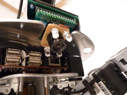
Owing to last year's disappointment with the light conditions during the approval phases (very different light conditions in different parts of the playing field, hard shadows, yellow lights...), I decided to add some powerful white LEDs on the camera to try to have at least a spot of well-lighted ground... cmucam_lights.jpg
Neato LDS

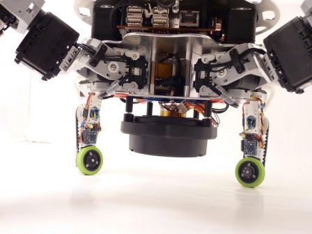
The lidar is mounted upside down, below the body. During normal operation, the sensing plane of the LDS will be around 8 or 9cm above the ground, and it's aim will be to detect obstacles I can't go over (like the opponent :p ). I'm still working on a protective cage around the sensor to avoid any damage to it. I don't want to know if it can support the full robot weight ;). Lidar_mounted.jpg
As always, a lot more pictures are available in the gallery!
Saturday, February 26 2011

Shinny!

Behold Xachikoma's new aluminum body!

mP1000772_1365x1024.jpg

Also to try and improve the quality of the pictures, thanks to my friend Landry I have a new big lightbox (still a WIP though)!

A lot more photos - and a more convenient viewer - in the gallery!

Tuesday, February 8 2011

Cut Belts and 3D printed pulleys

Driving the wheel without ruining the general shape of the Xachikoma leg has proved to be an interesting problem.

Also, remember that I'm not a mechanical engineer, so I may miss some well-known techniques and solutions here and there.

TachiLegs

<otaku>

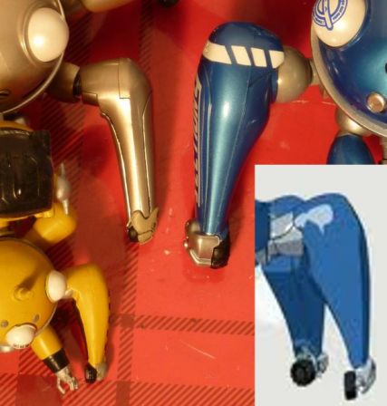
Tachikoma leg shapes are a little different from a source to another, even when you consider sources related to the first season only. Each action figure has its own, and even in the anime it's not extremely consistent between the opening credits, the cell-shaded ones you see during the episodes and the hand-drawn ones in the art-books.

</otaku>

Now back to the robot. The main concerns when designing the tibia were:

  • keeping down the leg width around the wheel (for aesthetics and to avoid blowing the max perimeter too quickly)
  • closed-loop control of the wheel.
  • control precision: little or no backlash, no slipping.
  • having a way to tell if the wheel is touching the floor or not
  • decent driving speed (30cm/s at least)
  • being able to switch from fixed to powered to free wheel.

The last one has been abandoned, due to the complexity it would add. Too bad, the Xachikoma will not be able to actually skate like last year's robot (but it still can fake it ;) ).

First designs had either the wheel directly on the motor or a gear-based transmission, both of which had advantages but were at the time way too large since I wanted to use an optical encoder for control. This led me to consider using another synchronous transmission that allowed more freedom for relative placement of the driving and driven axes: a timing belt. I also came across an off-axis magnetic encoder, that allowed me to reduce width even more.

The size of the magnetic ring for the encoder (32mm diameter) determined the minimum size of the wheel, and from there I chose the Banebot 41mm, 30A shore, as it has very good grip and the tire is fused with the wheel core, so no risk of slipping. Only problems would be the color, and the non-metric grub screw I had to buy an hex key specifically for... why on earth put a non-metric screw on a hub with a metric, 4mm axis?

Now with the size of the wheel determined, I had to start looking for pulleys that could make this mechanism a reality.

Pulley design

First thing I learned when looking at the pulley offer is that I would not find easily what I wanted. Whatever the type and size of timing belt (and there are a lot), impossible to find a pulley that is either less than 20mm wide or reasonably priced (often neither on nor the other). So I chose to make my own, 3D printed.

Choosing the type of belt got down to the question "what kind of pulley teeth are big enough to be accurately 3D printed, and small enough so the ~25mm of diameter pulley would have at least two engaged at any time". My choice went to the HTD 5M specification, since its size is OK (5mm from one tooth to the next), it's availability at various short length is very good and it's a metric belt, not an imperial-unit-based one. The smallest standard width however is 9mm, way too much for me, all the more considering the extremely low torque it would have to transmit. After cutting a few belts to see the smallest width I could reach, I settled for 3mm, to be perfectly sure I keep at least one inextensible thread intact in each belt.

Then I had to design the pulleys themselves. It's surprising to see how little information is available online on timing belt teeth. I had to cross reference various slightly different designs from different manufacturer to get something susceptible of functioning.

Pulley Design

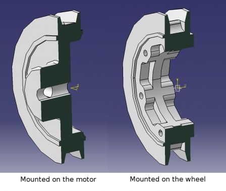
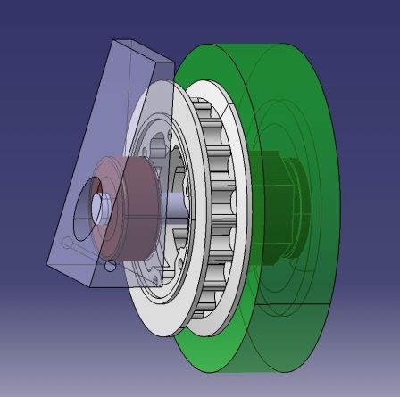
The one mounted on the motor is made so it covers partially the motor, and has a central hub with perpendicular holes for two grub screws. The other does not have a hub, but instead has a hole large enough to let the Banebot wheel hub through, and 6 threaded holes for screwing it to the wheel (only 3 would have been enough but the other are there for backup, if one thread is damaged). This allows for easier assembly and disassembly.

Cutting the belts

To reduce cost, I bought two 15mm wide HTD 5M belt with the idea of using one for tests and cutting the other in 5 pieces, so as to have one spare belt.

My first try was to put a cutter blade on a 3mm spacer, and turn the belt against it... took me some time but the result was nice. Problems: it took half an hour, I nearly cut my finger twice, and blunted the cutter blade completely. The teeth are very hard and trying to cut them like you cut your steak, going back and forth with the blade, tends to take a long time and kill the blade in the process.

Second try, with scissors, was a big failure, with uneven width.

So I made this little one-time-use tool from stuff lying around.

On a base plate, there is a 3mm spacer, on which is bolted a cutter blade. A pole is mounted for the belt to press against. You maintain the belt firmly against the base plate and the pole with the thumb while pulling it with the other hand, and in 30 seconds you have a shiny new 3mm wide belt (actually, the width is more around 3.2mm since the blade has its own thickness... Should have accounted for it when choosing the spacer). Also, no need to change the whole blade each time, just break the tip after two cuts and start again.

Current state

As seen in the previous post, I received the parts not so long ago, including the 3D printed pulleys from i.materialise.

Here is what the whole tibia looks like, still without electronics.

Tibia partially assembled

Tests with the belts showed a little too much friction here and there, mainly due to the fact that my cutting technique is not very accurate (width precision is around +/- 0.2mm I would say) and the printing material is a little rough. A solution I'm looking into is to add a little bevel to the side of the belt teeth, and so far it looks promising.

Most of the requirements should be met, at the exception of the powered/free/fixed wheel modes and maybe ground detection. After seeing the amount of tension needed for the belt, I think my initial plan to sense when the wheel touches the ground with a FSR will not work. The sensor seems to be already under too hight pressure compared to what will be added by supporting the weight of the body. Testing will tell, but considering that on these sensors resolution decreases when pressure increases, I'm not very confident :/

P.S : I'm all for open source, but cleaning things up to make them presentable takes time, time that I don't have much of, and time which is lost if nobody cares. If anybody is interested in further details, 3D models, etc, don't hesitate to say it and I'll try to release stuff.

Friday, February 4 2011

Lots of parts

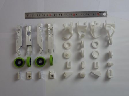
This week and the last, I received all the CNC milled and 3D printed parts for the legs!

mP1000640_1365x1024.jpg

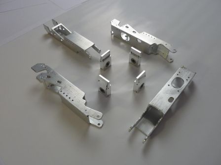
CNC milled goodness

The main element of the tibia is carved into 20x20x1.5mm square tubes (many thanks to the guys at AIPL!). The smaller part is used to support the wheel axis, and fits inside the tube. Having the two ball bearing fit tightly inside the bloc proved to be a challenge as the first ones I bought were a little too cheap and deformed when inserted. Sourcing parts from a better supplier solved the problem, but I still lost a week on this ><.

cncedparts

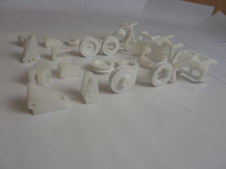
Sweet 3D printed stuff

printedparts

Then we have all the 3D printed stuff, made by the awesome guys at i.materialise. I designed five different parts, three of which are printed in ABS (ivory white) for rigidity and dimensional accuracy, and the other two in polyamide (white) for better details. It's interesting to see that in fact polyamide can be pretty rigid too when used with >4mm thick walls.

This "big" and convoluted part makes the junction between the Dynamixel servos and the custom made tibia. I noticed quite a few design faults (a missing bevel here, a hole too small there...), but nothing unsurmountable. I should probably have made it with bigger walls: it deforms a little too much to my taste when twisted along the longitudinal axis (which will happen in normal operation). Also it's a little too fragile around the hole where the ball bearing is inserted. I actually cracked one when trying to put the bearing the first time... luckily I could repair it by putting a droplet of acetone on the crack. After 5 minutes the two sides were neatly fused together again.

This one holds the servo used to orient the wheel (14g, 1.4kg.cm, analog, metal gears). Its axis is aligned with the contact point between wheel and ground, hence no need for tremendous torque.

I had a little surprise when I drilled the holes... some support material was left inside the part, and when the drill bit hits this material, it makes a breaking sound... Gave me quite a scare, I thought the drill bit or the part had just shattered ^^".

Last ABS printed one. It serves two purposes: providing a second attach point on the servo axis, and holding the motor in place at an adjustable position. While it does perfectly well at the first task, I'm afraid I kind of messed up concerning the second one.

The motor is clamped between the two flexible sides of the part. Two screws and nuts passing through the holes above and below the motor provide the clamping action. From the few test I have made so far, this system is able to block the motor in place, but it pretty quickly start to slip under the action of the tension of the belt. Also, signs of fatigue are visible on the part, as well as cracks around the holes... I think I will need to redesign it to be less adjustable (now I that I have the whole system at hand, I know the desired position of the motor with a very narrower margin) and more robust. I also think will not rely and the material flexibility this time, and/or I'll switch to polyamide.

Last but not least, the two pulleys. I received three of each in polyamide and one of each in ABS, and all of them are perfectly functional. I'll go into more detail about those in a future post.

Final words

I find the overall quality of the assembly extremely good, however I'm not used to playing with such precision tools, so maybe I'm easy to impress. Compared to the hand-made stuff I did until now, it's a big leap in term of quality and repeatability!

I'm pretty satisfied with the 3D printed parts (except the motor support). It's the first time I use this kind of service, and it opens a whole new world of possibilities, at an affordable prince.

Here are at random a few things I learned along the way (take it with a grain of salt): - if you want to have a screw or an axis going through a hole, make it the right diameter from the get go. - if you want to tap a hole, make it smaller than the recommended initial drill diameter, 0.2mm less if it's polyamide, 1mm less if it's ABS. - ABS is easy to drill and easy to tap, polyamide is relatively easy to drill but not that easy to tap. Use the 3rd tap a few times if you have important length of nylon screws to put in... - always check, check and check again your CAO before sending the parts for printing -_-"

Anyway, now I have to work on redesigning the problematic part, then assembling all of these, and do all the electronics and wiring... still a lot of work left.

Wednesday, February 2 2011

Beacon mast

Eurobot is a competition heavily promoting fair-play. One aspect of it is that robots must be able to avoid accidental collisions with their opponent (of course, plain and simple aggression is also completely out of the question!).

To make this task easier, the rules allow you to add to your robot a mast where the other team can place a beacon. This way, it's possible to have a constant, know element on any robot you play against.

Now this is all good and well, but this mast must stay at a fixed height at all time, and remain perfectly level... not exactly easy with a robot that can translate and rotate it's body! The mast is optional, yet choosing not to have one means direct elimination for any match where the opponent has a beacon, not a risk I'm willing to take (we only have 5 official matches, I don't want to play even less :/ ).

So here is my take on this problem: make a dynamic beacon mast, that stays level and at the correct height when the body moves.

Dynamic beacon mast gallery here

The mast is made of 3 Dynamixel AX-12+. The two lower servos control the height and the forward-backward orientation of the support, while the upper is mounted to tilt the platform left and right. The up-down amplitude is of around 8cm, and the tilt angles are more than what the body can do, so no worries on the movement amplitude front. What is a little more uncertain is the precision of support attitude when it has a 300g beacon on it. Further test is needed to be sure it's really stable and precise enough to be accepted at the competition.

Control of this appendage can be performed in two ways: either put sensors to sense the platform attitude and heigth, or compute the servos position with IK, just like we already do for the legs. I wouldn't mind strapping the top platform with an IMU and use this data for lateral stabilization, but when it comes to maintaining a precisely fixed height, it would be a little more complicated... so I will go with the second option.

Finally, this fixed, stabilized elevated platform seems like a good place to put the camera that will look at the whole playing field. The goal of this one will hopefully be to help spot the best action to do. The camera is a Playstation Eye, that I chose for its rapid shutter (up to 60fps at 640x480, 120fps at 320x240). While I won't be analyzing the video feed on the fly, having a camera that can take a picture in 1/120th of a second instead of 1/30th sure looks like a good idea on a moving robot ;)

Sunday, December 12 2010

Design of the Bioloid-based Xachikoma for Eurobot

At first, the Xachikoma project was completely separate from my participation to Eurobot. However, building two complex robots at the same time would have been way too time consuming, and nearly impossible to financially overcome. That's why, as I hinted in previous posts, I chose to merge the two projects into an Eurobot-playing version of the Xachikoma.

Of course, the two projects had different goals: one needed to be able to play by this year's Eurobot rules, whatever its means of achieving it, when the other had to look and act accurately like a Tachikoma... Not exactly a perfect match!

So the idea is this: build a robot which has the possibilities of moving like a Tachikoma (legs with enough degrees of freedom (DOF) and powered wheels), fitted with lots of sensors and equipments to be able to score some points and not be ridiculously unadapted for the competition, all of this without giving too much importance to the cosmetic aspect. This way, I can work on the mechanics, electronics and leg movements this year, and make an accurate-looking Tachikoma later. Also, I don't want to show up at the competition with a robot so unadapted it would have to rely on luck to be accepted past the approval phase. That would be kind of wasting the time of the referees and other participants.

The main structural differences between the original robot and the one I'll make this year are these: the Xachikoma won't have a pod, and probably no arms or eyes either :/ . The body, while still round, will be significantly different from the cute rounded blue shell we are accustomed to. On top of the body will probably be a moving structure destined to maintain the beacon support at exactly the right height and inclination whatever the body movements. On the bottom part of the body, the Neato Piccolo LDS (Laser Distance Sensor, aka the lidar I referred to in previous posts) will be mounted head down, but this still needs some consideration...

The chassis of the robot is heavily based on the Bioloid Premium Kit I talked about earlier. This is the core of the robot: 16 AX-12+ (at least 4 of which will be replaced by AX-18F), plus custom parts for the body itself and the tibia. With the AX-12+ and even more powerful AX-18F, the robot will be able to easily bear the payload (Beagleboard-xM, Neato LDS, PSEye camera, controllers, batteries, dynamically stabilized beacon support, other sensors...).

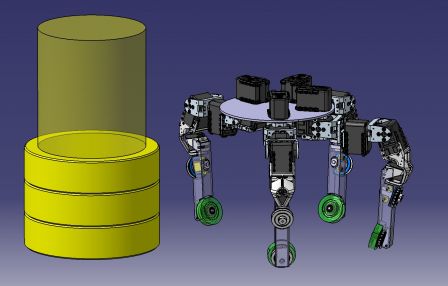
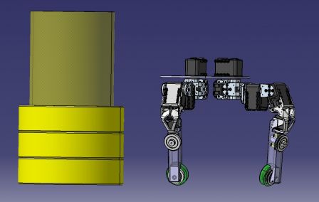
For size comparison, here is the chassis (I just began the 3D model of the body) next to a tower of playing elements. The perimeter when standing like that is a little below the 120cm mark, and it can easily be shrunk or widened by changing the leg's position. Chassis Tachi_45.jpg

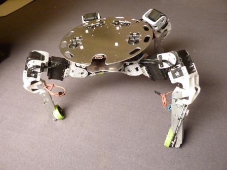
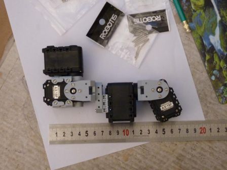
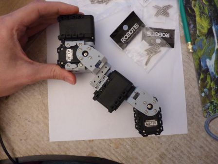
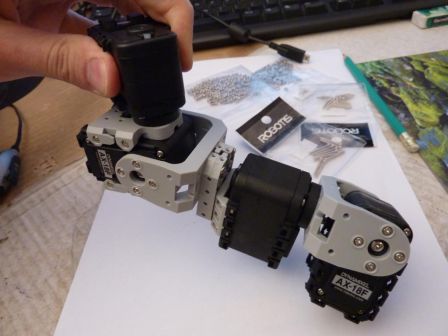
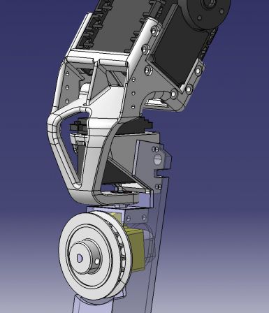
The leg has two parts: the first one is fully built from the Bioloid Premium Kit elements, and goes from the body to the knee. It is composed of 4 Dynamixel servos, arranged to have kinematics identical to the Xachikoma prototype, and to the Tachikoma. Particularly, the axes of the first three servos are concurrent, and the axes of the last two as well. mP1000486_1024x768.jpg mP1000489_1024x768.jpg mP1000487_1024x768.jpg

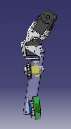
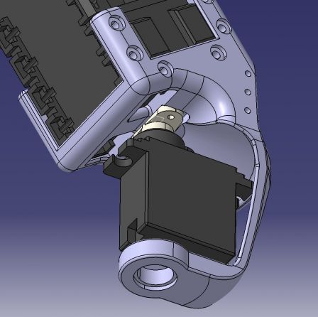
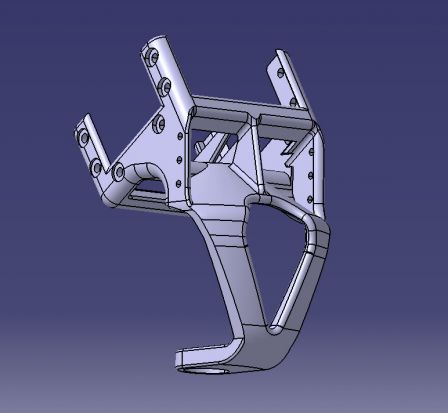
The second part of the leg is custom made, and goes from the knee to the wheel. It's composed of (from top to bottom): a servo support (weird shaped white piece, 3D printed), a metal-geared digital micro-servo, a second servo support (second white part, 3D printed), the tibia cut out of a 20x20 aluminum tube, a motor with its bracket (yellow part), two pulleys(also 3D printed) and their timing belt (not shown), and a wheel. Add to this a force sensor to know when the leg is on the ground, a magnetic encoder for motor control, probably one or more contact or proximity sensors, and a Baby Orangutan to manage all of this.

Tachi_tibia_30.jpg

The wheels are nice and have good traction. Only problem could be the color (green!) ^^. The rotation axis of the small servo passes through the contact point of the wheel with the ground, which has the advantage of not affecting too much the kinematics of the rest of the leg.

The servo supports are tricky parts: they must allow for +/- 90° rotation of the lower part of the leg, and yet be able to support all the weight of the robot, even with occasional shock. And on top of that, as it's the outermost part of the leg, it has to be as small as possible to avoid breaking the perimeter limit. It also mustn't get in the way of the tibia movement by reducing the range of the other servos of the leg. All these consideration led to this (arguably efficient) design.

Tachi_tibia_12.jpg

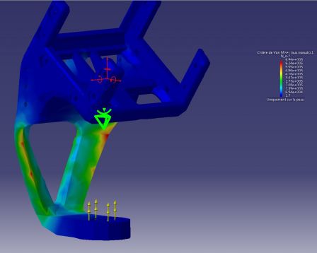
They will be printed in ABS plastic by the cool guys at i.materialise. ABS is a strong and rigid material, with a is very dimensionally stable and accurate printing process (meaning the part has little risk of being deformed while printed). Using Finite Element Analysis, the profile of the part has been refined to remove as much as possible the weak points of the design. Here is what I got on one of these tests: Tachi_tibia_13.jpg As you can see, the stress is spread across the whole lower part, with two potential small weak spots (in red). The first iterations had just one big crimson area at the bottom of the part, so this is an improvement ^^. Have a look here for an interesting tutorial about FEA.

The pulleys are more of a bet. I wanted a way to drive the wheel without slipping, yet I did not have enough space to fit gears, or commercially available timing belt pulleys... so I will try to print them with white polyamide (called "white, strong and flexible" by Shapeways).

Tachi_tibia_31.jpg

Tachi_tibia_32.jpg

The belt will be a 225 5M HTD (225mm length, 5mm between two teeth, High Torque Drive), but with non conventional width. I will try to reduce it to around 3mm, instead of 9. This would allow for pulleys to be way smaller (7mm width instead of the commercially available 20mm). I redesigned the pulleys from what I could find about the 5M HTD specification (ie. not much), and took this chance to make them just the way I need to mount on my mechanism. For example, I added a small ring on the side of the pulley that will allow perfect centering of the multi-pole magnetic ring that goes with the magnetic encoder (the blue ring). The pulley on the wheel will be mounted with six nylon screws onto the wheel, while the one going on the motor will fit on its shaft with a M3 grub screw.

Quite a few details are still in the design phase (like the body... a big detail!) but this is all I can show right now :)

In the next few weeks I should finalize this design, have the plastic parts printed, the aluminum part CNCed and the other parts shipped or hand-made. To be continued !

Tuesday, December 7 2010

Pololu and i.materialise

New language, new sponsors

Pololu

Logo_Pololu

Once again, the nice guys at Pololu agreed to support us :)

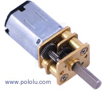
MotorHP Inside each leg, I will use one of these wonderful little motors. These are the same ones that I used two years ago, on XD Team's first robot! They pack some impressive punch for their size, and it shows on the current consumption (1,6A when stall) ^^. Just don't forget to add noise filtering capacitors!

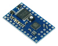
BBO And in equal numbers, there will be Baby Orangutan B-328 boards. These boards are a little smaller than Sparkfun's Arduino Mini Pro, yet they pack the same controller (ATmega328) and a dual motor controller! The trade-of is that you have to program them directly via ISCP. They will be used as auxiliary processor, in charge of managing a leg (motor, encoder, sensors) each.

i.materialise

And now a new partner: i.materialise ! These guys have probably the most complete offering in terms of 3D printing I know of. Just check their website, have a look at the various materials the offer! With them, the goal is to print the complex parts that can't be easily made by hand. They also provide much needed expertise to get it right :)

TibiaSupportPreview

Parts like this one for example would not be very nice to build by hand (more explanations on why the hell I think I need such a part later) ^^

Saturday, May 8 2010

J -pasbeaucoup

Il reste... grosso modo 5 jours, et le robot n'est toujours pas homologuable.

Au chapitre des trucs qui font pas plaisir, la CMUcam a décidé qu'avoir 4 ports servos c'était trop, alors elle en a tué 2. Après arrachages de cheveux et tests, la source de l'avarie n'a pas été formellement identifiée mais le problème a été réglé en utilisant les deux restants.

Sinon, niveau choses qui marchent :

- La balise à mettre sur le support surplombant le conteneur a été réalisée avec une bouteille de Yop, une pile 9v, un régu ajustable et quelques leds blanches. Les couleurs sont faites en scotch d'électricien.

Éteinte:


Allumée :

Pouvoir l'allumer est important pour avoir des couleurs facilement reconnaissables quelles que soient les conditions d'éclairage. Je m'en fais pas trop pour les matchs officiels, où l'éclairage est extrêmement puissant, mais plus pour tout ce qui viens avant : tests et homologations.

La luminosité est réglable pour pouvoir avoir toujours des couleurs bien saturées, mais pas complètement cramées. Ça fera déjà un truc qui ne nécessitera pas de calibration avant les matchs...

L'algorithme de recherche de la balise est codé, et donne des résultats plutôt satisfaisants : il trouve sans problème la balise même a 4m de distance, est plutôt rapide (recherche dans l'image en multi-résolution) et ne risque pas trop de faire de faux-positif.

- la détection de l'adversaire avec les capteurs ultrasons est fonctionnelle, et envoi à la carte principale un angle à fuir ainsi que l'intensité de la répulsion. La balise à poser sur l'adversaire est faite avec un fond de bouteille... ca fait un petit peu cheap mais bon ^^'. Plus de détails après la coupe, ou en regardant le code sur le svn.

- la boussole fait bien son boulot de boussole et permet au robot d'avoir une idée d'où regarder pour trouver la balise.

Voila, maintenant il reste beaucoup de code a faire/finaliser/tester pour la camera, mais la majorité des algorithmes important sont faits, donc ce qu'il reste est plutôt orienté "faire marcher en conditions réelles ce qui marche deja sur des cas de test".

Monday, April 5 2010

Premier lancé de tomate

3 semaines à faire de l'élec de façon intensive, et maintenant le robot commence à pouvoir faire des trucs :)

lol


Bonus : lancé de tomate !

Friday, February 26 2010

Un peu plus de mouvements...

Après une longue attente que je pensais briser en annonçant que le dossier projet était validé, que l'équipe était enfin officiellement inscrite, etc. Hé bien non, on attends encore... donc pour patienter, voila une petite vidéo de la base roulante du robot !

- page 2 of 3 -