Xevelabs

To content | To menu | To search

Tag - bioloid

Entries feed - Comments feed

Monday, April 14 2014

GlitchBot

I recently posted about the new XL-320 servos by Robotis. I got 4 of these, and thought I should do a quick demo with them before the long and grueling groundwork that will be needed to integrate them in my new robot which will mix AX and XL servos.

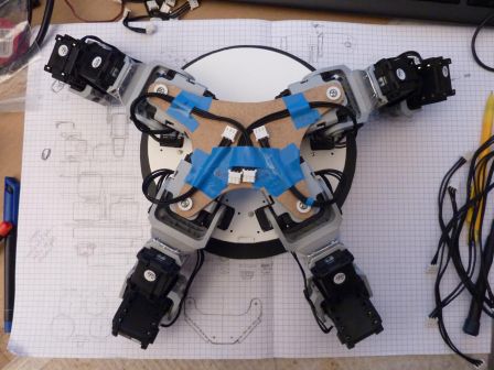
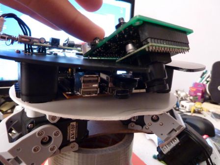
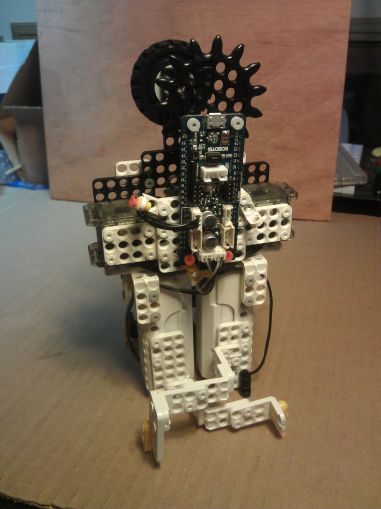
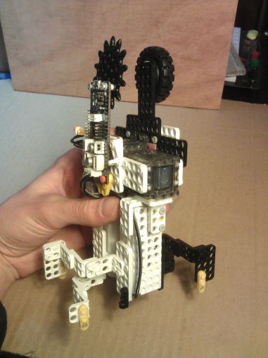
So here is GlitchBot, a little walker robot. It uses 3 XL-320 servos, the OpenCM9.04 and OLLO parts exclusively.

2014-04-03_22.15.20.jpg

2014-04-03_22.15.33.jpg

GlitchBot walking

I'll have to make steps smoother... here it goes forward thanks to the silicon foam it's walking on, but on my desk it just shuffles in place :p

The design is based on Tictac6 / Twitch / TwitchMX robots. It's basically a 3-servos hexapod that is in fact more of a biped, depending on how you look.

The principle is simple enough: one servo to rotate each leg, and one to swap which trio of feet is on the ground, with a deformable parallelogram configuration to keep the legs parallel to each other.
Each leg is made primarily with one of the batteries, put as close as possible. Flex in the material is taken into account to keep the bot level when it is standing on one trio of leg.

2014-04-03_22.16.11.jpg

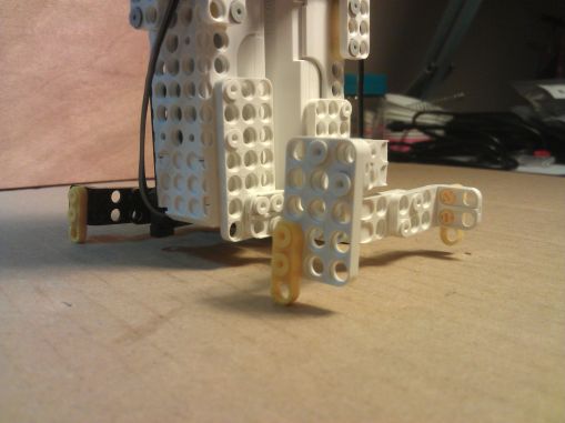
One leg up... there's enough clearance, it's all good!

There is a little glitch sometimes where a command is not executed (which results in this video in the turn, near the end)... I guess the bot is aptly named ^^' I'll have to investigate.

Here is the sketch for OpenCM9.0: GlitchBot.ino

More technical discussions in this thread on Trossen Robotics Forum.

Dynamixel XL-320

I received recently some Dynamixel XL-320 servos for beta-tesing. These are the new mini servos of Robotis' Dynamixel family. They are intended to be used for small robots that do not need a lot of torque, like the cute Darwin-Mini. Yet, what I would really love to do with them is to put them on a bigger robot, with AX and MX servos altogether. I envision a bot where joints could have the proper size of actuator, all the way from the MX-106 for knees and load baring joints to the XL-320 for fingers, sensors, or cosmetic movements (let's make the ears of Darwin-OP wiggle!).

Interfacing with AX / MX servos

Yet, there are 4 major differences that makes these small actuators not so simple to use with their bigger brothers:

  • they are intended to run at 7.4V instead if 11.1V, meaning you can't just put them on the same power supply rail,
  • they have smaller, 2mm pitch Micro-Latch Molex connectors that are incompatible with the Molex Spox 2.50mm of the AX and MX,
  • they use the newer Dynamixel Protocol v2.0, same as the much much bigger Dynamixel Pro. (This was not the case for some earlier beta testers, but since the support website page has been changed, I believe it's going to stay like that from now on).
  • they do not have regular mounting holes for M2 screws, they are intended to fit with OLLO plastic parts and their plastic rivets, meaning they have 4mm holes every 6mm (where AX have 2mm holes every 8mm, and MX have a variety of (non-compatible >_<) hole patterns).

When it comes to the first and second problems, a solution can be found with an adapter board. Aaron Perkins did just that, and I intend to make one too at some point - a smaller and less expensive one though.

The third one is not that bad, since commands in both protocols can be sent in turn on the same line, and there is no risk of misunderstanding. Only difficulty is that the master has to be able to speak fluently in both protocols.

When it comes to interfacing the servos mechanically with other stuff, there are multiple ways to go at it. The most obvious would be to use OLLO parts and rivets, just as intended, but this is not compatible with AX/MX servos, and there is a lot of give in every assembly. Rivets are great for small fun robots or prototyping but n match for screws when you want the thing to stay like that and not wobble around.
In the Bioloid Premium kit, they use a few OLLO-compatible parts, for example in the head to fit the ZIG-110A radio module. This is achieved with what look like M2.5 thermoplastic screws. They have a head with a diameter of 4.3mm, which is enough not to go through the 4mm holes of the OLLO parts.
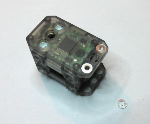
M2 screws have flat heads around 3.6mm of diameter, but with the help of a small M2 washer (diam 5mm), they can be used to bolt the OLLO parts to regular AX parts. 5mm happens to be exactly the size of the small recess in the parts, in which the shoulder of the rivet usually fits.

XL-320_washers.jpg

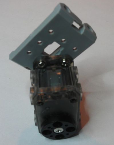
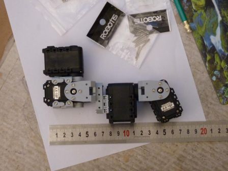
Still, the difference in hole pitch (one every 8mm on AX servos, one every 6mm on the XL-320) will necessitate more work to use them together. The smallest simple pattern to fit OLLO parts on AX parts would be to put 5 OLLO holes (4x6mm = 24mm between the two further apart) aligned with 4 AX holes (3x8mm = 24mm), but this arrangement is not very practical. Also, 3 Ollo holes align well enough with 2 AX holes in diagonal to attach (like in the picture), yet I can't see it as a real solution for most cases...

XL-320_on_AX_part.jpg

I guess I'll work on some 3D printed mechanical adapter parts.

Other thoughts

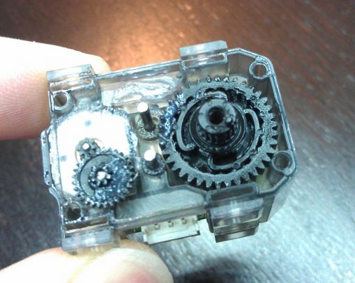
The gearbox is 100% plastic, even the motor gear. However, there is a nice feature on the output gear: a torque limiter (the sort of double lobe thingy inside the biggest gear in the photo). This should make breaking the gears less likely in case of shock (like having a robot fall from a table).

XL-320_torque_limiter.jpg

The build quality is really good, the architecture is no-fuss, with one PCB on which the motor, STM8 microcontroller and potentiometer are soldered directly.
The sensor is an old-school potentiometer, like the good-old AX servos. There is enough room to put a magnetic sensor like in the MX servos, but the price would have certainly been much higher - such sensors cost maybe $4 more than the potentiometer, and I'm not even counting the magnet and increase of assembly and testing cost.

Some more references

Here are the references of the connectors for the XL-320 (that can be found also here).

  • Male header, 3 ways: 53253-0370 (vertical), 53254-0370 (right angle)
  • Female housing, 3 ways : 51065-0300
  • Contact (24-30AWG): 50212-8000 (reel), 50212-8100 (bag)

More details on the XL-320 page on Robotis support website

Friday, January 17 2014

USB2AX firmware update

- this dates back a few weeks, but I forgot to publish it! -

The updated firmware guide is available on the documentation wiki!

Recently, I got reports of USB2AX units that did not function properly with Robotis' Dynamixel wizard. Those were brand new units, and multiple simultaneous hardware failures seemed unlikely. Time to investigate.

On my computer, nothing strange, as always, the famous "It works for me" syndrome. However, I noticed that a RoboPlus update was available, and, thinking nothing of it, I started downloading it while searching for a way to repeat the problem at home.

As you might have already guessed, the new version of RoboPlus turned out to be the trigger element, and what is comes down to is the addition of support for Dynamixel PROs.

It appears that the Dynamixel PRO line uses a different protocol named Dynamixel 2.0. This protocol is more complex than DXL 1.0, with more header bytes (4!), longer adresses (2 bytes) and longer CRC (2 bytes), and a lot of new commands and cool features.

The fun thing with the Dynamixel Wizard is that even when you want it to search for DXl 1.0 devices, it sends a DXL 2.0 broadcast ping. And this ping looks like a DXL 1.0 packet addressed to 0xFD (the id used by the USB2AX), with a length of 0 bytes (which does not play well with DXL 1.0 as it's supposed to be >= 2), and a command ID of 0xFE.

As Murphy's law dictates, this ping 2.0 just so happened to fall in what seems to be the only place in the USB2AX parsing state machine where it could be stuck... which explains that after that, nothing would work anymore.

This is a good reminder why testing inputs with fuzzing techniques and trying to make completely fool-proof input parsing code is important. Luck has it that something will always happen to your program fail even when it is very unlikely.

Wednesday, April 4 2012

USB2AX mini

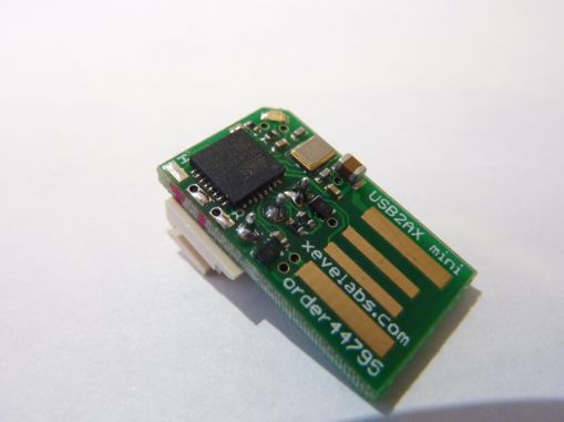
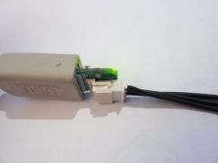
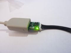
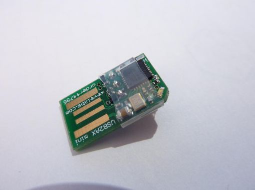
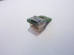
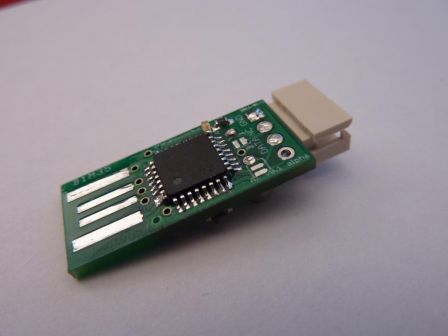
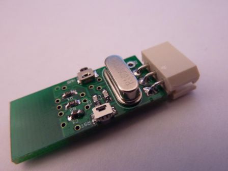
The USB2AX project is still on track (more on that in a next post). As a little side-project, I wanted to have a try at making the USB2AX even smaller while retaining all the current characteristics (ATmega32u2, ESD protection, LED, etc). That's how the USB2AX Mini came to be.

USB2AX_Mini___12_.jpg

The motivation is just to have fun and satisfy my lust for optimization. Or some might say pseudo-optimization here since by over-optimizing size, some other aspects of the device suffer, like quality of the physical connection (resistance to vibrations and yanking). But hey, this one will most probably never go beyond the prototyping stage, so please leave it to that.

I wanted to stay away from some obvious ways to make it smaller, like putting components on both side, using components too-small-to-be-soldered-with-my-crappy-prototyping-tools, requiring custom mechanical parts (like the ones used in the miniature bluetooth or WiFi dongles, with the electronics inside the USB plug) or cutting functionalities (ESD protection, status LED...). Thus it had to be possible to assemble with the same tools I already use and keep the nearly the same BOM as the v3.0. Working on the connectors seemed like the way to go, as they occupy around 75% of the board real estate.

The ideas here are:

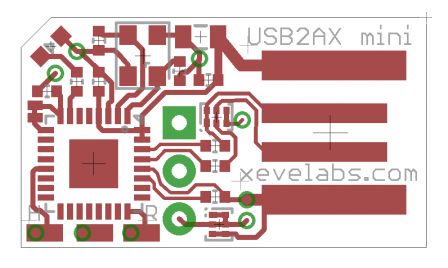
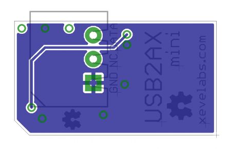
  • use a PCB USB connector, with gold fingers this time (saves 10mm)
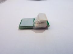
  • move the dynamixel connector so it is the closest possible to the USB plug, on the other side of the electronic components (saves around 5mm)
  • route the USB lines between the Dynamixel connector's pads (saves still a little bit more)

And that's the result:
usb2ax_mini_top.png
usb2ax_mini_bot_mirror_.png

With a total length of around 22mm (compared to the 37mm of the V3.0), it already looks a lot smaller. However, by moving the Dynamixel connector a few millimeters inside the PCB, the actual length when measuring the device with a Dynamixel cable plugged in is 17mm shorter (41mm for the v3.0)!

From an electronics standpoint, it's nearly identical to the USB2AX v3.0. The only thing that changed is that instead of protecting each line of the serial port with a 47ohm and the anti-ESD chip, and then connecting them, I connected them directly then protected the remaining DATA line.

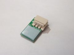
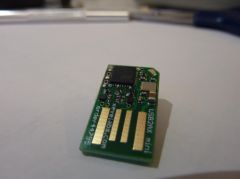
USB2AX_Mini___15_.jpg USB2AX_Mini___11_.jpg

The PCB USB plug has, as expected, some disadvantages. Without modification, you have poor or non-existent electrical contact, that can be fixed by increasing the plug thickness with a piece of tape (here, I use 0.5mm thick Teflon tape). I could have had the PCB made with 2mm thick material, but it costs a lot more with Seeedstudio Fusion. The problems I used to have (see v1.0) with the electrical contact quality have been fixed by getting the board gold-plated (ENIG), with additional gold fingers on the contact pads.

USB2AX_Mini___20_.jpg USB2AX_Mini___19_.jpg
It feels like you are plugging the Dynamixel cable directly into the USB port :P

USB2AX_Mini___21_.jpg USB2AX_Mini___22_.jpg USB2AX_Mini___24_.jpg

I tried to protect the board with some heat-shrink tubing, but it tends to slip when shrinking, I had to do it 3 times to get this result.

All in all, I think it's a fairly cool little board, and it still does its job, so I'm happy with it :) As always, code and files are available in the Git repository :)

Thursday, November 24 2011

USB2AX

It's about time I talked about this one. This post has been a work in progress for more than 6 months!

The idea behind the USB2AX

The USB2AX board is the small programmable USB to AX and MX-series Dynamixel adapter we designed with my friend JLG, in the early stages of developing the Xachikoma.

Basically, it's a gizmo you plug into an USB port that creates a virtual COM port on your computer, through which you can communicate to Dynamixel servos. It behaves much like the USB2Dynamixel made by Robotis (in most cases, it's a drop-in replacement), but is limited to AX and MX series servos. It does not provide power to the servos, this has to be done by other means like using a SMPS2Dynamixel Adapter or a home-made power cable.

I made the design (mostly from things I learned from the Arduino Uno and Adafruit ATmega32u4 Breakout Board+, but adding my own n00b mistakes), and he made the first versions PCB, under the constant pressure of me asking to make the board smaller, SMALLER, SMALLER!

USB2AXv1_top.jpg
USB2AXv1_bot.jpg
Version 1

Making such a beast is far from being a new idea, yet my version is the smallest of the "clean" ones I know of, and it's more versatile than most. I would not have made it if I did not have a real need of it: I use 4 of them in the Xachikoma.

The core of the project is an ATmega32u2, a 8 bits micro-controller from ATMEL without much bells and whistles, but with a full-speed USB device port and an UART. Its little brother, the ATmega8u2, is used to replace the FTDI in the Arduino Uno, and its bigger cousin the ATmega32u4 will be the heart of the upcoming Arduino Leonardo. Having a micro-controller do the bridge between USB and the half-duplex serial bus used by Dynamixel actuators is interesting for two reasons: you can use software tricks to create the half-duplex line instead of having multiple components, and you can create more complex firmwares which not only channels bytes from one side to the other, but can perform treatments on them.

The half-duplex trick used here is the same some people use to make an Arduino talk to Dynamixels by just tying TX and RX together. This is also used by the Arbotix controller and others, just to name a few sources you can learn from. The idea is that in the ATmega, you can turn ON and OFF each part of the UART (receive, transmit), and when one is not used, the corresponding pin can be left floating (meaning it does not impose a particular logic level to what it's connected to). This way, you can leave the receiving part ON most of the time, and switch to transmitting mode only when you have bytes going from the computer to the servos.

The ability to update and experiment with the firmware is potentially a great strength: not only can you optimize the inner workings to lower the latency (compared to the usual FTDI chip), but you can also add nifty features by allowing the USB2AX to understand what it receives and to react to it. Instead of only transmitting bytes blindly, you can imagine implementing macro commands, like a SYNC_READ (iBot has done so). Another possibility is to change completely the way the computer sees the board. For example, you could make a joystick with force-feedback based on Dynamixels, and program the USB2AX to appear to the OS as a plug&play joystick, allowing seamless use of your über-joystick in any game!

Some inspirational material around the topic of "stuff speaking with the dynamixel actuators":
http://billyzelsnack-robotics.blogs...
http://www.siempreaprendiendo.es/pr...
http://www.pablogindel.com/2010/01/...
http://websvn.hylands.org/listing.p...
http://robosavvy.com/forum/viewtopi...

Latest developments

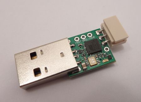
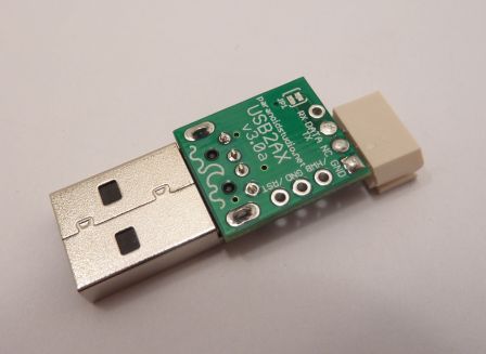
The latest version is the V3.0a (V2 never actually lived :/), and improves durability and reliability while still keeping a small form factor. Basically, this version should be roughly on equal footing with the USB2Dynamixel from Robotis when it comes to communicating with AX-series Dynamixels, just smaller and with slightly lower latency.

USB2AXv3.0a_top.JPG
USB2AXv3.0a_bot.JPG
The latest V3 prototype.

With a real USB plug, the risk of shoddy connection should be reduced close to zero. This causes a problem however, as the standard male Type A USB plugs are 20mm long, more than twice the size previously allocated to the plug and more than two third of the total length of the original board! That's why we remade the PCB from scratch, with better layout, smaller traces and smaller components where possible (0.5mm pitch QFN package for the ATMega32u2, small SMD crystal, 0402 capa and resistors...), even if it means that it can no longer be assembled with the good old soldering iron. That's an opportunity to practice reflow soldering with a hot plate, yeah :D Also added from the first versions are the recommended decoupling caps (!) and ESD protections on both USB and serial lines, to reduce risks of frying the board or any of the costly equipment connected to it.

USB2AXv3.0a_conn_bent_top.JPG
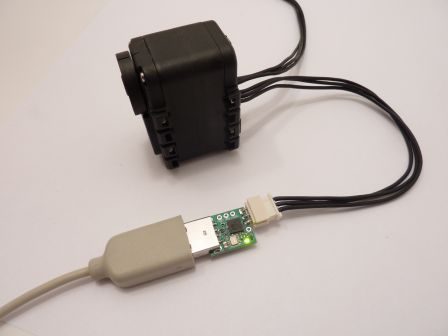
a V3.0a, plugged and connected to an AX-12+.

P1010183.JPG
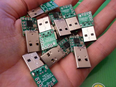
It took me a few afternoons to make all of these, mostly by hand...

USB2AX documentation, schematics, BOM, code

(and if you may wonder: ParanoidStudio is the name under which we hack robotics stuff with this friend).

I still have a few units of the improved version (better quality and durability). If you are interested in buying one, please say send an email at xevel {at} xevel |dot| fr ! A commercial version will most likely see the light of day in a few weeks/months too.

Some threads with information and discussions about this version: http://forums.trossenrobotics.com/s...
http://robosavvy.com/forum/viewtopi...
http://forums.trossenrobotics.com/s...

Next time, I'll talk a little about the first prototypes of USB2AX, I had some real fun doing this...

Tuesday, April 5 2011

Nearly final sillouette

A lot happened since last post, and things are getting very close to their final shape.

Xachikoma_20110404_1.jpg

Xachikoma_20110404_2.jpg

The robot got some brand new 3D printed motor mount (thanks i.materialise!), all the required electronics in the legs, a second camera and a rotating laser distance sensor (the Neato LDS, from the XV-11 vacuum cleaner robot)!

New 3D printed parts

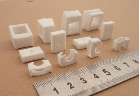
From front to back row: a part used to lock the ball bearing in place, the lower bearing mount and the motor mount, motor_mounts.jpg

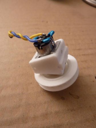
That's what the motor + motor mount + pulley looks like when everything is assembled. This goes inside the aluminum tube. The motor is taken between two layers of 0.25mm aluminum sheet. With this, there is no risk of deformation of the polyamide part, plus it allows for two M2 grub screws (both in the bottom of the part, one close to the front, one close to the back) to secure the motor and reductor in place without blocking the gears. motor_mounted.jpg

The motor mount and the part with the ball bearing are now two distinct elements. With the new motor mount design, it was necessary to split the two, as one is fixed and the other has to be adjusted to have the right belt tension. support_bearing.jpg

My first thoughts when I designed the mechanism was that little to no effort would apply to move the bearing out of its hole, but torsion in the tibia support part quickly showed that it was not the case. This little part keeps the bearing where it is. Here it's demonstrated with an old motor mount. bearing_lock.jpg

Leg Control Board

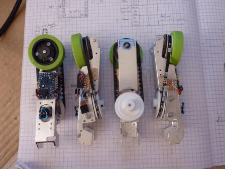
Each leg is fitted with a Baby Orangutan B-328 that controls the motor, the magnetic encoder, the wheel orientation servo, and talks on the Dynamixel Bus as a real Dynamixel device. Right now, it masquerades as an AX-12+ and can communicate with Roboplus :)

finished_lower_tibias.jpg

In order to have it talking on the Dynamixel bus, I had to apply two important modifications on the B-328 board: change the oscillator to a 16MHz one, and remove the user LED (the red one).

Having a 16MHz oscillator instead of a 20MHz one is needed to join the bus at 1Mbaud. I found the perfect replacement here (Murata CSTCE16M0V53-R0) .

The LED had to go because it's tied to the ATMega328p's UART TX, and caused the idle tension on the line to be as low as 1.8v (using only the inbuilt PD1 pull-up resitor) when it should have been 5v. This does not play nice with the original usb2dynamixel, which often saw 0x00 bytes that were not there. Unsoldering (or... destroying -_-") the led solved the problem.

CMUcam3

Having a second camera might seem overkill, yet it addresses one of the most important sensory question for this year's competition: "what color is the square In front of me?". It also be used for line-following, and identification of the team's color at startup (one less switch to flip myself... yeah I'm lazy like that ;) ).

I will write a simple custom firmware for it, that will probably do segmentation (it's quite easy in HSV with the colors used on the playing field and playing elements), basic line following, and maybe some rough position tracking based on the grid. The observable area varies with body height and rotations, and the lens distortion is quite important in the corners. Fun times ahead to extract meaningful information ^^.

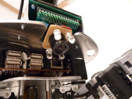
Owing to last year's disappointment with the light conditions during the approval phases (very different light conditions in different parts of the playing field, hard shadows, yellow lights...), I decided to add some powerful white LEDs on the camera to try to have at least a spot of well-lighted ground... cmucam_lights.jpg

Neato LDS

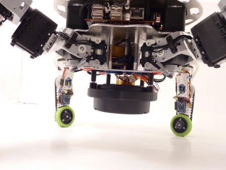
The lidar is mounted upside down, below the body. During normal operation, the sensing plane of the LDS will be around 8 or 9cm above the ground, and it's aim will be to detect obstacles I can't go over (like the opponent :p ). I'm still working on a protective cage around the sensor to avoid any damage to it. I don't want to know if it can support the full robot weight ;). Lidar_mounted.jpg

As always, a lot more pictures are available in the gallery!

Friday, February 11 2011

Some leg movements

These legs have some real potential for doing fun stuff :)

Go watch on Youtube, 1080p!

Some (unpowered) leg movements

Tuesday, February 8 2011

Xachikoma body prototype

At some point last month, before I received any of the manufactured parts, I became tired of building the robot only as a CAD model, and wanted to make some physically tangible progress.

So I disassembled completely the Bioloid humanoid, and started assembling the Dynamixel part of the legs. The two plastic plates in the middle of the leg proved to be too flexible, so I replaced them with a 3mm aluminum part. I also took this opportunity to correct the alignment of the third servo axis, so that it intersects with the axes of the first two servo in a single point.

But that was not enough for my thirst of physical manifestation, so I built a prototype of the body, using black and white 2mm styrene sheets. It works as a prototype, but I would not even try to have it walk with such a flexible body.

I later replaced the bottom plate by a more rigid 3mm medium one.

mP1000574_1365x1024.jpg

Wiring still needs a little work, but I like where it's going :)

Having the things in my hands made me see how big it will be, and how I could improve a few things. For example, I adjusted the distance between the front legs so that the Beagleboard fits snugly with my shortened RS-232 connector plugged in.

I also added the CMUcam3 as a giant color detector, watching the ground. It will be in charge of looking at the grid to provide absolute positioning information every time the robot crosses a line, and also will be used to dock nicely on the playing element the robot wants to move. The idea is to have an easy alternative if I can't get a reliable positioning system using only the Neato LDS lidar, as it won't be parallel to the ground most of the time! Communication between this camera and the Beagleboard will use the shortened RS-232 showed above.

mP1000584_1365x1024.jpg

Tadaaa!

Wednesday, February 2 2011

Beacon mast

Eurobot is a competition heavily promoting fair-play. One aspect of it is that robots must be able to avoid accidental collisions with their opponent (of course, plain and simple aggression is also completely out of the question!).

To make this task easier, the rules allow you to add to your robot a mast where the other team can place a beacon. This way, it's possible to have a constant, know element on any robot you play against.

Now this is all good and well, but this mast must stay at a fixed height at all time, and remain perfectly level... not exactly easy with a robot that can translate and rotate it's body! The mast is optional, yet choosing not to have one means direct elimination for any match where the opponent has a beacon, not a risk I'm willing to take (we only have 5 official matches, I don't want to play even less :/ ).

So here is my take on this problem: make a dynamic beacon mast, that stays level and at the correct height when the body moves.

Dynamic beacon mast gallery here

The mast is made of 3 Dynamixel AX-12+. The two lower servos control the height and the forward-backward orientation of the support, while the upper is mounted to tilt the platform left and right. The up-down amplitude is of around 8cm, and the tilt angles are more than what the body can do, so no worries on the movement amplitude front. What is a little more uncertain is the precision of support attitude when it has a 300g beacon on it. Further test is needed to be sure it's really stable and precise enough to be accepted at the competition.

Control of this appendage can be performed in two ways: either put sensors to sense the platform attitude and heigth, or compute the servos position with IK, just like we already do for the legs. I wouldn't mind strapping the top platform with an IMU and use this data for lateral stabilization, but when it comes to maintaining a precisely fixed height, it would be a little more complicated... so I will go with the second option.

Finally, this fixed, stabilized elevated platform seems like a good place to put the camera that will look at the whole playing field. The goal of this one will hopefully be to help spot the best action to do. The camera is a Playstation Eye, that I chose for its rapid shutter (up to 60fps at 640x480, 120fps at 320x240). While I won't be analyzing the video feed on the fly, having a camera that can take a picture in 1/120th of a second instead of 1/30th sure looks like a good idea on a moving robot ;)

Sunday, December 12 2010

Design of the Bioloid-based Xachikoma for Eurobot

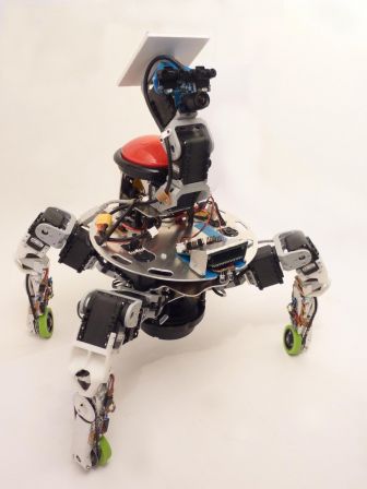
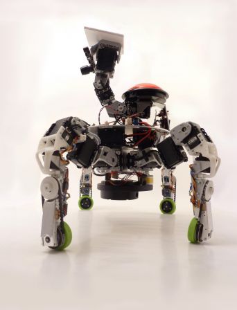
At first, the Xachikoma project was completely separate from my participation to Eurobot. However, building two complex robots at the same time would have been way too time consuming, and nearly impossible to financially overcome. That's why, as I hinted in previous posts, I chose to merge the two projects into an Eurobot-playing version of the Xachikoma.

Of course, the two projects had different goals: one needed to be able to play by this year's Eurobot rules, whatever its means of achieving it, when the other had to look and act accurately like a Tachikoma... Not exactly a perfect match!

So the idea is this: build a robot which has the possibilities of moving like a Tachikoma (legs with enough degrees of freedom (DOF) and powered wheels), fitted with lots of sensors and equipments to be able to score some points and not be ridiculously unadapted for the competition, all of this without giving too much importance to the cosmetic aspect. This way, I can work on the mechanics, electronics and leg movements this year, and make an accurate-looking Tachikoma later. Also, I don't want to show up at the competition with a robot so unadapted it would have to rely on luck to be accepted past the approval phase. That would be kind of wasting the time of the referees and other participants.

The main structural differences between the original robot and the one I'll make this year are these: the Xachikoma won't have a pod, and probably no arms or eyes either :/ . The body, while still round, will be significantly different from the cute rounded blue shell we are accustomed to. On top of the body will probably be a moving structure destined to maintain the beacon support at exactly the right height and inclination whatever the body movements. On the bottom part of the body, the Neato Piccolo LDS (Laser Distance Sensor, aka the lidar I referred to in previous posts) will be mounted head down, but this still needs some consideration...

The chassis of the robot is heavily based on the Bioloid Premium Kit I talked about earlier. This is the core of the robot: 16 AX-12+ (at least 4 of which will be replaced by AX-18F), plus custom parts for the body itself and the tibia. With the AX-12+ and even more powerful AX-18F, the robot will be able to easily bear the payload (Beagleboard-xM, Neato LDS, PSEye camera, controllers, batteries, dynamically stabilized beacon support, other sensors...).

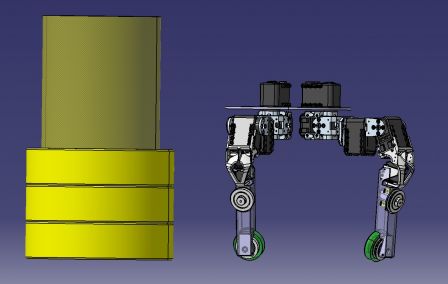
For size comparison, here is the chassis (I just began the 3D model of the body) next to a tower of playing elements. The perimeter when standing like that is a little below the 120cm mark, and it can easily be shrunk or widened by changing the leg's position. Chassis Tachi_45.jpg
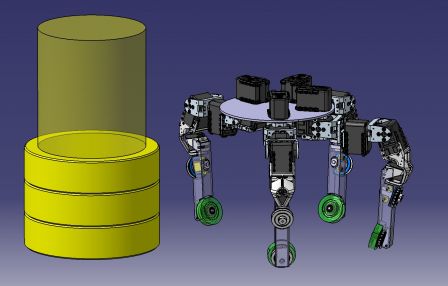
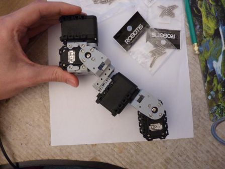
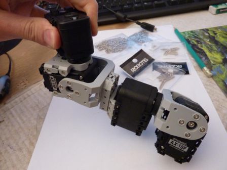
The leg has two parts: the first one is fully built from the Bioloid Premium Kit elements, and goes from the body to the knee. It is composed of 4 Dynamixel servos, arranged to have kinematics identical to the Xachikoma prototype, and to the Tachikoma. Particularly, the axes of the first three servos are concurrent, and the axes of the last two as well. mP1000486_1024x768.jpg mP1000489_1024x768.jpg mP1000487_1024x768.jpg
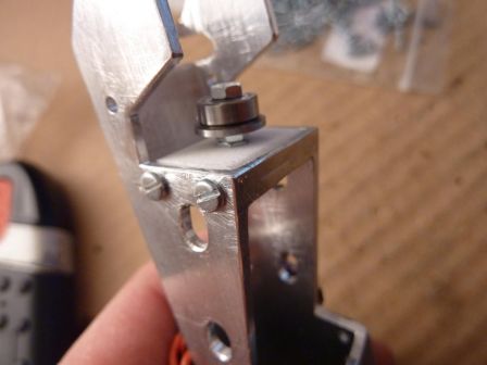
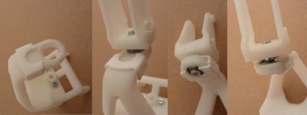
The second part of the leg is custom made, and goes from the knee to the wheel. It's composed of (from top to bottom): a servo support (weird shaped white piece, 3D printed), a metal-geared digital micro-servo, a second servo support (second white part, 3D printed), the tibia cut out of a 20x20 aluminum tube, a motor with its bracket (yellow part), two pulleys(also 3D printed) and their timing belt (not shown), and a wheel. Add to this a force sensor to know when the leg is on the ground, a magnetic encoder for motor control, probably one or more contact or proximity sensors, and a Baby Orangutan to manage all of this.
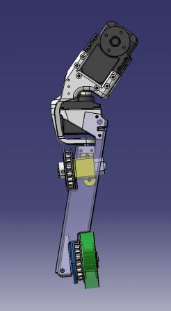
Tachi_tibia_30.jpg

The wheels are nice and have good traction. Only problem could be the color (green!) ^^. The rotation axis of the small servo passes through the contact point of the wheel with the ground, which has the advantage of not affecting too much the kinematics of the rest of the leg.

The servo supports are tricky parts: they must allow for +/- 90° rotation of the lower part of the leg, and yet be able to support all the weight of the robot, even with occasional shock. And on top of that, as it's the outermost part of the leg, it has to be as small as possible to avoid breaking the perimeter limit. It also mustn't get in the way of the tibia movement by reducing the range of the other servos of the leg. All these consideration led to this (arguably efficient) design.
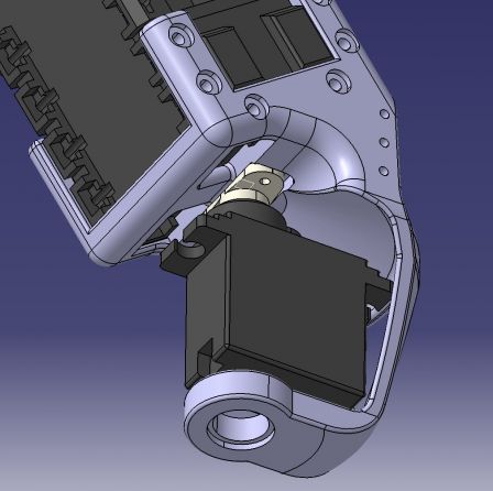
Tachi_tibia_12.jpg

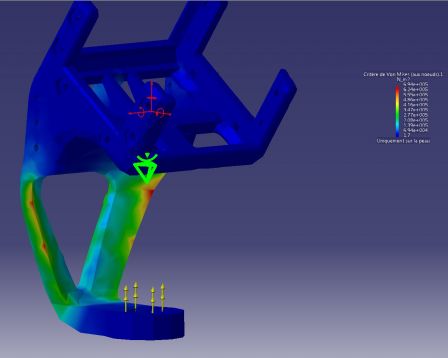
They will be printed in ABS plastic by the cool guys at i.materialise. ABS is a strong and rigid material, with a is very dimensionally stable and accurate printing process (meaning the part has little risk of being deformed while printed). Using Finite Element Analysis, the profile of the part has been refined to remove as much as possible the weak points of the design. Here is what I got on one of these tests: Tachi_tibia_13.jpg As you can see, the stress is spread across the whole lower part, with two potential small weak spots (in red). The first iterations had just one big crimson area at the bottom of the part, so this is an improvement ^^. Have a look here for an interesting tutorial about FEA.
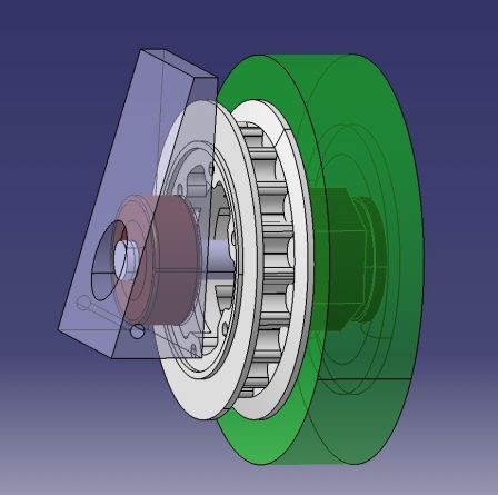
The pulleys are more of a bet. I wanted a way to drive the wheel without slipping, yet I did not have enough space to fit gears, or commercially available timing belt pulleys... so I will try to print them with white polyamide (called "white, strong and flexible" by Shapeways).
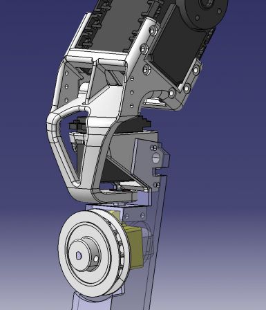
Tachi_tibia_31.jpg

Tachi_tibia_32.jpg

The belt will be a 225 5M HTD (225mm length, 5mm between two teeth, High Torque Drive), but with non conventional width. I will try to reduce it to around 3mm, instead of 9. This would allow for pulleys to be way smaller (7mm width instead of the commercially available 20mm). I redesigned the pulleys from what I could find about the 5M HTD specification (ie. not much), and took this chance to make them just the way I need to mount on my mechanism. For example, I added a small ring on the side of the pulley that will allow perfect centering of the multi-pole magnetic ring that goes with the magnetic encoder (the blue ring). The pulley on the wheel will be mounted with six nylon screws onto the wheel, while the one going on the motor will fit on its shaft with a M3 grub screw.

Quite a few details are still in the design phase (like the body... a big detail!) but this is all I can show right now :)

In the next few weeks I should finalize this design, have the plastic parts printed, the aluminum part CNCed and the other parts shipped or hand-made. To be continued !
- page 1 of 2