USB2AX: the early days...
By Xevel on Thursday, November 24 2011, 18:09 - USB2AX - Permalink
And now for a small lesson in ghetto prototyping, I present you the first two USB2AX!
v0.1
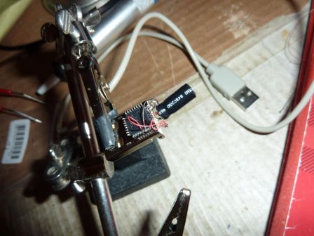
When you don't want to bother with a PCB...
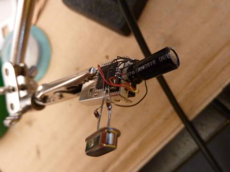
The very very first proto was a horrible mess. I had bought two ATMega32u2 in TQFP package, but without any idea on how to make the first version of the board. And suddenly, the idea to just not make one crossed my mind. All the wiring is done using Teflon-coated 36awg multi-strand found on a popular RC hobby website (I love this stuff, so thin!).
A few hours later I inserted this monster into an USB port of my computer, only to be greeted with... nothing. I thought the internal 8MHz oscillator of the ATMega would be enough to program it with the USB bootloader, but I was wrong, as I could have known had I RTFM a little more carefully.
So I installed a big through-hole 16MHz quartz I had lying around and began to look for pump capacitors I had not even thought of ordering. I finally unsoldered two from a nondescript board I had in my "electronic stuff" box, where I put all the scavenged treasures I always dream of making something from, and hardly ever do. The values might not be right, but it did the trick and I could witness for the first time the apparition of an "Atmel DFU" device in the device manager of my WinXP laptop! (At the time, Win7 64bits did not recognize the signature of the drivers provided by Atmel. This has been corrected.) That was enough to motivate me to continue working on the project, hopefully with some hardware that does not threaten to break just by looking at it!
v0.2
A few days later, JLG made the first version of the (2-sided) PCB, and I went to have some made with the good old etching method. One problem with that was the vias. The board had to have a few of them, and I could not find a suitable drill to bore them... so I had to improvise again. Meet the Punk USB2AX!
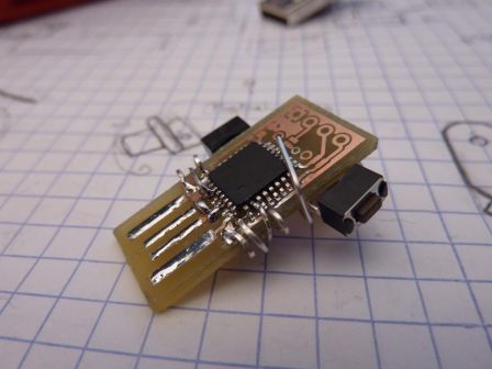
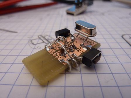
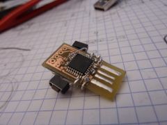
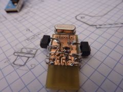
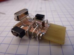
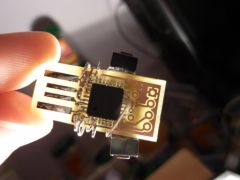
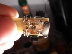
When you have a 2-sided PCB and no drill small enough to make the vias... let's just say "A man's gotta do what a man's gotta do" ;)
Some simplifications were made, again, when assembling it. The two 22ohm resistors on the USB lines are omitted (saves a few vias, and even if it's baaaaaad, it works...), and I did not put the LED and its resistor. Each remaining via is replaced by a ring made from through-hole component leads (these are always useful!), placed so that it would not touch any other of these "external via", or any component. For a small board like this one, it works surprisingly well. Once this board gave sign of life and had been tested with the USB to Serial example of LUFA, I could safely order professionally-made ones on BatchPCB.
That's it for today! Next time, I think I will talk about all the tribulations involved in turning the USB2AX into a commercial product! ^^
