Xevelabs

To content | To menu | To search

Subcategories

Monday, October 13 2014

Aringer

Small robots are cool, big robots are awesome.

A few years ago, I met this cool guy, who happens to be a wonderful artist : Romain Lardanchet.
He does these sculptures where he takes parts of scooters / motorbikes / quad, re-interpret them to look like living thing, a process he calls "mechamorphosis" ^^.

When I met him, he had this awesome 3m long mechanical panther with him, Agheera. The idea to work together on making something like that move immediately came to mind, sparks flew, and a year and a half later (December 2013), when we finally could find some time off from the rest of our busy lives, we started working on something together.

2014-02-16_12.31.41.jpg

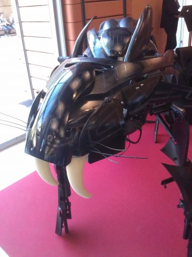
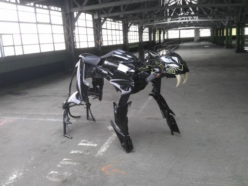
The result is Aringer, a saber-tooth tiger with an animated head. He did the body, we made the head together, and another talented friend made the beast purr, growl and roar.
3m long, 1.5m high and 1.2m wide, it's more or less the size of a horse, and can be ridden :)

WARNING annoying sound, turn your speakers down.

Head motino test

The head can move left and right, the 2 pairs of ears move up or down (a little like the beasts in Avatar!), the eyes glow, the lips move up and down. The "breathing" of the gills-like things was removed later due to the annoying sound.

Reaction test

The head moves left and right to follow the people in front of it thanks, and it will have different behaviors depending on the distance of the closest obstacle, from purring to threatening growl, to full on roaring for intimidation!

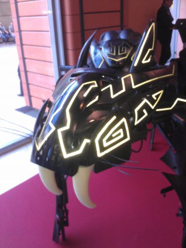
There is also a sort of easter egg for people who happen to take a photo with the flash:

2014-03-19_16.06.09.jpg 2014-03-19_16.06.18.jpg

The body is covered with patterns made with black retro-reflective tape. They light up but the effect can only be seen from the point of origin of the light, so only the person with the flash will see it :)

Romain (the artist) website: http://www.romainlardanchet.com/
Jean Charles (the sound creator) website: http://www.silenceprod.com/
More technical details on the Trossen Robotics Forum

Monday, April 14 2014

GlitchBot

I recently posted about the new XL-320 servos by Robotis. I got 4 of these, and thought I should do a quick demo with them before the long and grueling groundwork that will be needed to integrate them in my new robot which will mix AX and XL servos.

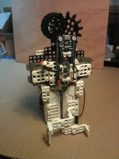
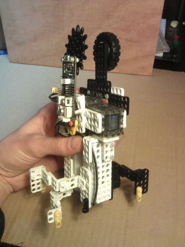
So here is GlitchBot, a little walker robot. It uses 3 XL-320 servos, the OpenCM9.04 and OLLO parts exclusively.

2014-04-03_22.15.20.jpg

2014-04-03_22.15.33.jpg

GlitchBot walking

I'll have to make steps smoother... here it goes forward thanks to the silicon foam it's walking on, but on my desk it just shuffles in place :p

The design is based on Tictac6 / Twitch / TwitchMX robots. It's basically a 3-servos hexapod that is in fact more of a biped, depending on how you look.

The principle is simple enough: one servo to rotate each leg, and one to swap which trio of feet is on the ground, with a deformable parallelogram configuration to keep the legs parallel to each other.
Each leg is made primarily with one of the batteries, put as close as possible. Flex in the material is taken into account to keep the bot level when it is standing on one trio of leg.

2014-04-03_22.16.11.jpg

One leg up... there's enough clearance, it's all good!

There is a little glitch sometimes where a command is not executed (which results in this video in the turn, near the end)... I guess the bot is aptly named ^^' I'll have to investigate.

Here is the sketch for OpenCM9.0: GlitchBot.ino

More technical discussions in this thread on Trossen Robotics Forum.

Dynamixel XL-320

I received recently some Dynamixel XL-320 servos for beta-tesing. These are the new mini servos of Robotis' Dynamixel family. They are intended to be used for small robots that do not need a lot of torque, like the cute Darwin-Mini. Yet, what I would really love to do with them is to put them on a bigger robot, with AX and MX servos altogether. I envision a bot where joints could have the proper size of actuator, all the way from the MX-106 for knees and load baring joints to the XL-320 for fingers, sensors, or cosmetic movements (let's make the ears of Darwin-OP wiggle!).

Interfacing with AX / MX servos

Yet, there are 4 major differences that makes these small actuators not so simple to use with their bigger brothers:

  • they are intended to run at 7.4V instead if 11.1V, meaning you can't just put them on the same power supply rail,
  • they have smaller, 2mm pitch Micro-Latch Molex connectors that are incompatible with the Molex Spox 2.50mm of the AX and MX,
  • they use the newer Dynamixel Protocol v2.0, same as the much much bigger Dynamixel Pro. (This was not the case for some earlier beta testers, but since the support website page has been changed, I believe it's going to stay like that from now on).
  • they do not have regular mounting holes for M2 screws, they are intended to fit with OLLO plastic parts and their plastic rivets, meaning they have 4mm holes every 6mm (where AX have 2mm holes every 8mm, and MX have a variety of (non-compatible >_<) hole patterns).

When it comes to the first and second problems, a solution can be found with an adapter board. Aaron Perkins did just that, and I intend to make one too at some point - a smaller and less expensive one though.

The third one is not that bad, since commands in both protocols can be sent in turn on the same line, and there is no risk of misunderstanding. Only difficulty is that the master has to be able to speak fluently in both protocols.

When it comes to interfacing the servos mechanically with other stuff, there are multiple ways to go at it. The most obvious would be to use OLLO parts and rivets, just as intended, but this is not compatible with AX/MX servos, and there is a lot of give in every assembly. Rivets are great for small fun robots or prototyping but n match for screws when you want the thing to stay like that and not wobble around.
In the Bioloid Premium kit, they use a few OLLO-compatible parts, for example in the head to fit the ZIG-110A radio module. This is achieved with what look like M2.5 thermoplastic screws. They have a head with a diameter of 4.3mm, which is enough not to go through the 4mm holes of the OLLO parts.
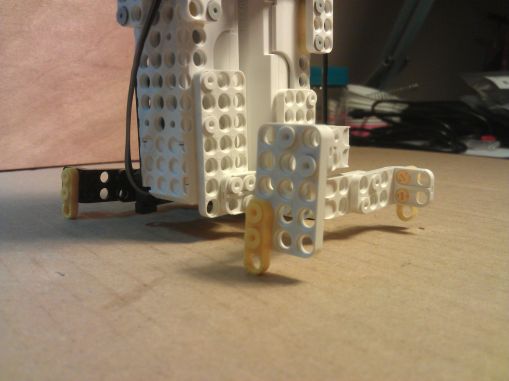
M2 screws have flat heads around 3.6mm of diameter, but with the help of a small M2 washer (diam 5mm), they can be used to bolt the OLLO parts to regular AX parts. 5mm happens to be exactly the size of the small recess in the parts, in which the shoulder of the rivet usually fits.
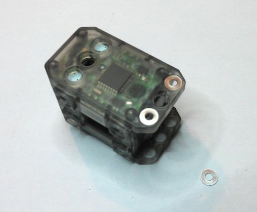
XL-320_washers.jpg

Still, the difference in hole pitch (one every 8mm on AX servos, one every 6mm on the XL-320) will necessitate more work to use them together. The smallest simple pattern to fit OLLO parts on AX parts would be to put 5 OLLO holes (4x6mm = 24mm between the two further apart) aligned with 4 AX holes (3x8mm = 24mm), but this arrangement is not very practical. Also, 3 Ollo holes align well enough with 2 AX holes in diagonal to attach (like in the picture), yet I can't see it as a real solution for most cases...
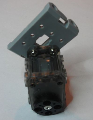
XL-320_on_AX_part.jpg

I guess I'll work on some 3D printed mechanical adapter parts.

Other thoughts

The gearbox is 100% plastic, even the motor gear. However, there is a nice feature on the output gear: a torque limiter (the sort of double lobe thingy inside the biggest gear in the photo). This should make breaking the gears less likely in case of shock (like having a robot fall from a table).
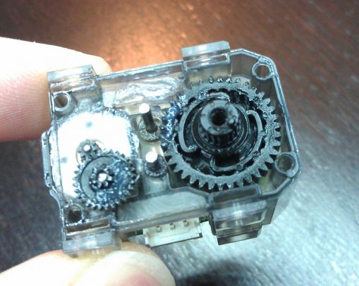
XL-320_torque_limiter.jpg

The build quality is really good, the architecture is no-fuss, with one PCB on which the motor, STM8 microcontroller and potentiometer are soldered directly.
The sensor is an old-school potentiometer, like the good-old AX servos. There is enough room to put a magnetic sensor like in the MX servos, but the price would have certainly been much higher - such sensors cost maybe $4 more than the potentiometer, and I'm not even counting the magnet and increase of assembly and testing cost.

Some more references

Here are the references of the connectors for the XL-320 (that can be found also here).

  • Male header, 3 ways: 53253-0370 (vertical), 53254-0370 (right angle)
  • Female housing, 3 ways : 51065-0300
  • Contact (24-30AWG): 50212-8000 (reel), 50212-8100 (bag)

More details on the XL-320 page on Robotis support website
Saturday, November 23 2013

Foldarap small upgrades

A little post to show two quick upgrades I made to my machine to make it much more easy to use:

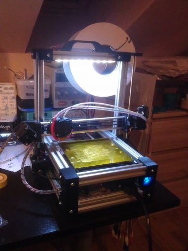
1) A spool holder. I used this one, made for the Foldarap, but it's completely not adapted to the way I want to use it as the spool I have is too big and touches the desk if mounted "properly"... So I purposefully misused it :)

Screwed in that position, the holder masks the 4 topmost centimeters of the build volume, but it works great otherwise. I might make a new one that folds into the handle some day ;)

2) There shall be Light, and there was Light.

Two LED strips (one on each side of the top aluminum frame) directly wired into the power supply, it helps a lot to see what is going on :)

The wires run inside the aluminum profile so as not to pose any problem when folding the machine.

2013-11-23_23.42.11.jpg

Friday, November 15 2013

Back in the game with Foldarap superpowers

Hey, long time not see. It's been a busy year. Things are moving again though :) Let's dive in!

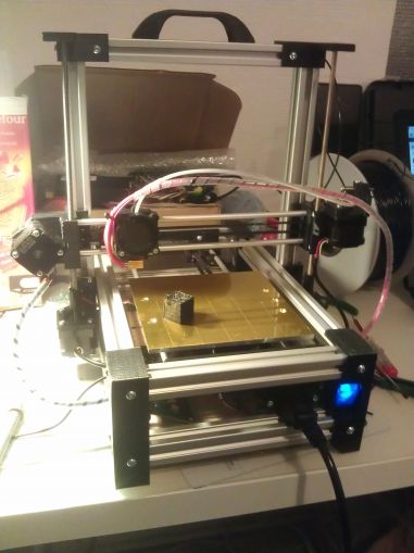
The most important news is that I am now the owner of a 3D printer, a Foldarap. It's a RepRap that has the cool feature of being foldable to the size of a briefcase. I got the "peer to peer" package of the ulule crowdfunding campaign, and had a friend print me the parts on his Solidoodle.

2013-10-26_01.06.47.jpg

This printer comes as a kit that cost me 500€, plus the parts I had my friend print.

First surprise when I tried to assemble a few parts, impossible to put the aluminum profiles in the 3D printed parts... It turns out that some of the parts might have to be printed at 101% to get the proper result... I should read the instructions sometimes ^^

So instead of re-printing anything, I carved the inside of each part with a Dremel and a small end-mill. Around 3h later I had all the parts down to size.

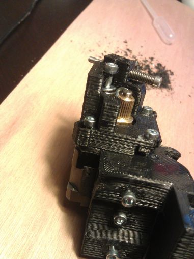
At some point, I realized one of the parts (the one that holds the extruder motor) was not the right one, I had the old model that accommodated a geared stepper, whereas my kit had the hardware to mount an extruder with a direct drive NEMA 14. Of course, the holes did not match, I had to modify the part... but it turned out OK, I have found the proper way to tighten everything and haven't even changed it since.

2013-10-22_23.34.35.jpg

The rest of the build went smoothly (well apart from when I made silly mistakes like mounting the plate that supports the bed upside down...), it's a great kit!

I started printing right away, and while the first print started very well, it turned to crap after before the end. The causes were that the temperature sensor was not mounted properly (the cable sometimes lost contact!), plus my inexperience that made me select an extruder temperature too low (190°C).

The printer itself is very stable, and as long as you feed it plastic reliably - which has been a problem until I raised the current of the extruder stepper to the suggested values and tightened the bolt on the idler... Even after traveling by train/bus/car and walking a lot, it is still perfectly ready to print as soon as I unfold it :)

Currently, I stopped using the heat bed, and put some UHU glue on it to get that damn 1st layer to stick. Now it sticks all right, maybe a little too much. Also, I now extrude at around 210°C, which gives me an awesome cohesion between layers.

I still haven't mastered it, but I get acceptable results, sometimes :p. It's a long road, but at least now I'm walking it instead of sitting on the side!

Saturday, November 10 2012

Deadbugging fine pitch BGA

When you don't have a breakout board to test that fancy new BGA chip you just received, you make do with what you have at hand.

After seeing a few posts about "deadbugging" (soldering wires to the leads or pads of a component instead of soldering it on its recommended footprint) of BGA chips on Dangerous Prototypes, some with "big" solder balls, and some with smaller ones, I thought I would share my latest attempt at it.

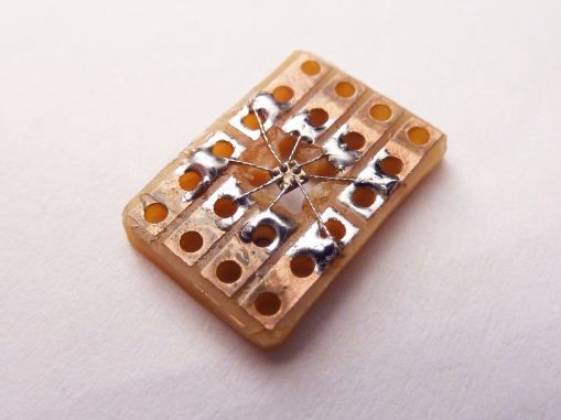
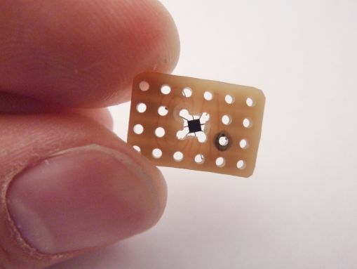
tmp006_deadbug_01.JPG tmp006_deadbug_02.JPG

The chip is the TMP006 from TI, a great little temperature sensor / infrared thermopile which, when properly soldered and calibrated, gives both the local temperature and the temperature of whatever is in front of it. The chip in itself might be inexpensive, I could not find a reasonably priced ready-to-buy breakout board. Dangerous Prototypes has a PCB, and TI sells a big and expensive evaluation module, and that's it.

The TMP006 is a 1.5mmx1.5mm component with 0.5mm pitch BGA featuring 8 connections. As the sensor in itself needs a line of sight with what you try to measure the temperature of, I started by making a hole in a piece of stripboard, then cutting andtinning the strips to get 8 pads all around the hole.
Then, one by one, with 36awg wire I connected the pads...

Deadbug soldering

And Voila :)
Notice the solder balls are lead-free and sometimes have a hard time melting with my overly-oxidized budget iron... :/
I had to re-solder two of them for which the solder ball did not melt enough the first time.

It's not necessarily the prettiest, but it worked well enough: I could get valid local temperature data, yet remote temperature was jumping all over. A quick look around the web and it seems that it is not unheard of for this sensor to report garbage when you don't follow the particularly specific footprint and assembly process.

Since the most pressing matter was to develop the low level driver, It was not completely in vain. Yet, I'll have to wait for the next prototype with the sensor properly soldered on the project board to finish the higher level code (calibration and computation of the remote temperature).

Do you want to know more ? Here is an excellent video from Dave of EEVBlog if you want more information on this technique : http://www.youtube.com/watch?v=q53u...

EDIT: After some time of use, it appears very clearly that this technique is NOT durable. The connections tend to break fairly easily. Better keep this technique for the times when there is NO alternative, and try to do it the right way (reflow soldering on an adequate PCB) otherwise.

Friday, January 6 2012

Hackerspace in Nancy

I'm now officially a member of the one and only NYBI.CC! (page on hackerspaces.org : http://hackerspaces.org/wiki/NYBI.C...)

Nybicc_square_180px.jpg

NYBI.CC, or NancY BIdouille Création Construction (roughly translates to tinkering, creating and "making stuff" (club) of Nancy ) is a young makerspace/hackerspace with already a lot of very cool people, working on projects as diverse as RepRaps, Remote Underwater Vehicles, FPGAs, NeufBox hacking, blinky stuff, mini laser engravers, educational projects of all forms, ...

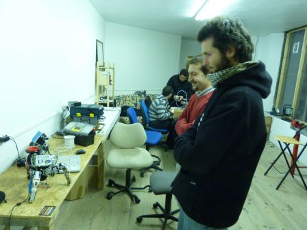
I've been coming to the weekly meeting on and off for a few month now (basically since all the ground work on the place itself is done : staircase, walls, lighting,... :P )

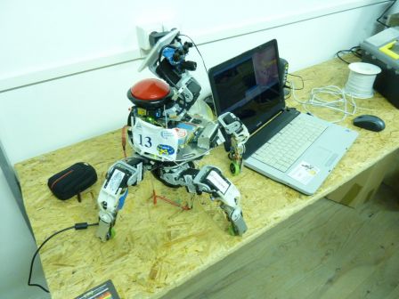
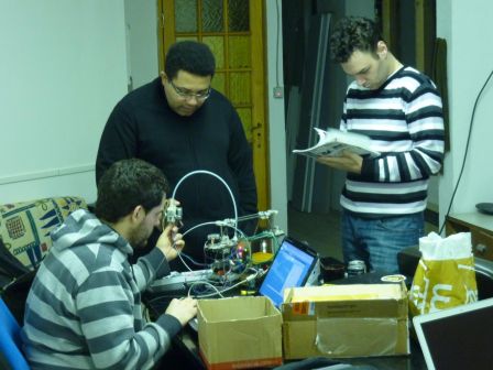
And on Wednesday, I also showed Xachikoma to the other members :) mP1010264_1365x1024.jpg
mP1010265_1365x1024.jpg

Meanwhile, a reprap was beening fixed... It's a nice little Huxley that suffered some damage, and they had, among other things, to straighten some PLA parts using a SMD rework station :D
Fun times ^^ mP1010266_1365x1024.jpg