Deadbugging fine pitch BGA
By Xevel on Saturday, November 10 2012, 05:43 - Hacking - Permalink
When you don't have a breakout board to test that fancy new BGA chip you just received, you make do with what you have at hand.
After seeing a few posts about "deadbugging" (soldering wires to the leads or pads of a component instead of soldering it on its recommended footprint) of BGA chips on Dangerous Prototypes, some with "big" solder balls, and some with smaller ones, I thought I would share my latest attempt at it.
The chip is the TMP006 from TI, a great little temperature sensor / infrared thermopile which, when properly soldered and calibrated, gives both the local temperature and the temperature of whatever is in front of it. The chip in itself might be inexpensive, I could not find a reasonably priced ready-to-buy breakout board. Dangerous Prototypes has a PCB, and TI sells a big and expensive evaluation module, and that's it.
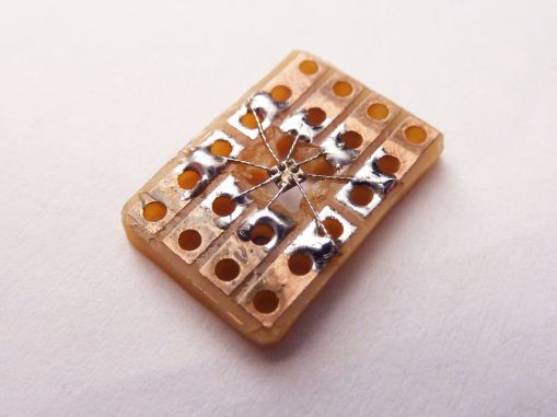
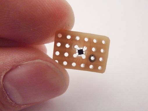
The TMP006 is a 1.5mmx1.5mm component with 0.5mm pitch BGA featuring 8 connections. As the sensor in itself needs a line of sight with what you try to measure the temperature of, I started by making a hole in a piece of stripboard, then cutting andtinning the strips to get 8 pads all around the hole.
Then, one by one, with 36awg wire I connected the pads...
And Voila :)
Notice the solder balls are lead-free and sometimes have a hard time melting with my overly-oxidized budget iron... :/
I had to re-solder two of them for which the solder ball did not melt enough the first time.
It's not necessarily the prettiest, but it worked well enough: I could get valid local temperature data, yet remote temperature was jumping all over. A quick look around the web and it seems that it is not unheard of for this sensor to report garbage when you don't follow the particularly specific footprint and assembly process.
Since the most pressing matter was to develop the low level driver, It was not completely in vain. Yet, I'll have to wait for the next prototype with the sensor properly soldered on the project board to finish the higher level code (calibration and computation of the remote temperature).
Do you want to know more ? Here is an excellent video from Dave of EEVBlog if you want more information on this technique : http://www.youtube.com/watch?v=q53u...
EDIT: After some time of use, it appears very clearly that this technique is NOT durable. The connections tend to break fairly easily. Better keep this technique for the times when there is NO alternative, and try to do it the right way (reflow soldering on an adequate PCB) otherwise.


Comments
Impressionnant !
Impressive. I am in awe. Kudos!
Chapeau bas :)
Thats impressive man. You must have very stable hands.
"...remote temperature was jumping all over. " I have the USB eval board for the TMP006. As I recall, that chip is equally sensitive to IR radiation from both the front side and the back side. That why you need to mount it backed against a solid IR-opaque surface with the same temperature as the chip itself, to get useful IR temperature readings.
How would you go about doing the same for a 4x3 array bga, with two pins on the inside/middle?
@JBeale: great info, I had not thought about it. I will give it a try, thanks!
Nice, might try this approach with some HV5523's.
Interesting re. mounting on a surface, what about using a piece of thermal pad on the back of the chip?
Might be a workaround for now..