PhantomX Reactor Arm (Part 2)
By Xevel on Saturday, March 16 2013, 23:38 - Permalink
First, a little feedback on the problems I had in Part 1, thanks to Tyberius of Trossen Robotics:
- Hex keys: already solved! Newer kits have good ones in a reasonable number :)
- Charred ABS: already solved! Newer kits will be made with Plexiglas-G, no more burnt black powder.
- Hubs: that's how they are nowadays when Robotis makes them :( I noticed the fault doesn't lie only on the hub (BTW, chubbiness is normal for these parts it seems), the brackets are at fault too, since the same hub can move freely in one bracket and not in another one. Possible solution: use a little file and adjust very slightly the hole in the bracket.
- Localized power cords: not gonna happen, it's understandably a logistical nightmare, and beside it's not that hard to replace just the offending cord or to have a $1 plug adapter.
As I'm going to move quite a lot in the next few days, I started assembling the rest of the arm before the base, with the goal of doing as much as possible without making the arm too big to be transported.
Upper Arm section:
Step 1: mount the thick plate rough side down. Be careful when inserting the screws not to remove the nuts... My advice: put a finger on the nut while you put the screw, then screw it at least half a turn before inserting the next, and at last tighten everything.
Step 4: if you get THAT, then you did it WRONG. 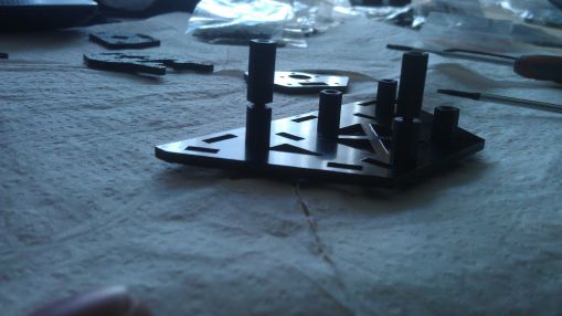 The screw goes through the plate, then in the 15mm standoff, and the 10mm F-F goes on the 15mm one.
Wrist:
Now it's getting technical. You have lots of alternatives (bracket F1 or F2, wrist rotation or not). I'll go with F2 and wrist rotation. All the pics in the manual are for F1. Since F2 is not symmetrical, put the over-hanging part of the Bottom Back Bracket on the opposite side of the bend of the F2 bracket, like that:
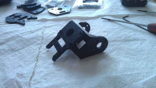
Wrist rotation servo:
Step 1: "Next mount the Top and Bottom Back Brackets to the back of Servo #7." The pic is not very helpful here: it means stacking the top Reverse Bracket on the Bottom Reverse bracket, and then putting the servo on top of that, like that.
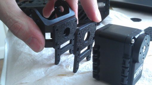
Actually, the picture two step later explains it well too. I put the rough facing the same direction, contrary to what the pics show, but it's not an important point.
All smooth up to the wiring step, that requires a tool to push the plug all to it's correct position. Now back to the gripper!
Gripper Assembly:
Ha! From the list of required tools, that's where the 2mm hex starts getting useful! My apologies four doubting you! .. Except there is no screw of this size in sight. :/ A relic of the past maybe. For some reason I got 4 gripper arms. In fact, I have double the number of each of the small parts (bushings, screws...) but the right number of big parts. It seems to be normal, and I like to have extra of the breakable and losable pieces :)
Step 1: 8mm screws... yeah, they are a little long and will scratch the side of the case, but that's nothing to be alarmed about. Step 2: building the washer assembly is a lot less fun. First try resulted in a crushed bushing as soon as I applied enough force to make it possible to drive the screw... Hopefully I had a lot of spare. Using a pair of pliers with little teeth helps a lot, and loosening the hole a little with the hex key (or best, a small drill - 1.7mm maybe? - if you have one). One modification to the washers that would make this operation a breeze would be to have a square flange => you could put the screw without having to apply pressure to the bushing itself, making this operation much easier and much less prone to damage the washer.
INTERLUDE: Here I took the train for the first part of the trip. The arm, unfinished, has been put unceremoniously in my luggage between my socks and t-shirts.
One of the things I find a little annoying in terms of design with this kit is that to access any interface between two assemblies, you have to disassemble nearly everything in reverse order up to that point. Let's say I want to change the hubs between the base and the runners: I have to separate the runners, which requires removing the plates between them, and also to disassemble the base to access the screws used to fasten the F1 brackets on servo 2 and 3. There is of course no way to check the tightening of all the screws quickly. And if for example you have one of the first nuts you put in this F1 bracket that decides it prefers its freedom while you are trying to carefully put a screw through it, then you are a sad panda >_>. It's exactly the same with the way the base is built: you can't for example remove it quickly to be able to fit the arm in your luggage. Modularity would be greatly appreciated.
Also, look at the servo #1. It is supposed to be coaxial with the giant ball bearing, but there is no play in the assembly to recover from any alignment errors that are made possible by the tolerances in the size of the holes of the various screws. The bearing itself has (as is expected of it) very little axial play. I chose to loosen the 4 screws between servo #1 and the pan plate, and I will try to re-tighten them once everything is in place, since they are nearly accessible even when the arm is fully assembled.
I chose not to use the Pan Cover, this way when the arm is folded it can rest on the outer ring of the ball bearing regardless of the arm orientation. Just a personal preference.
Mounting the Arbotix: I noticed one of the LED is broken.
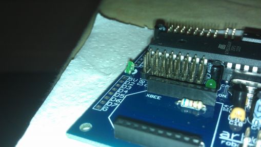
No trace of the missing part in the package, it happened before that. I'll change it somewhere down the line, not a big deal.
Yeah, all assembled! It looks awesome :) It's going to need its own bag next time I take the train ^^
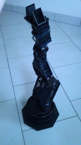
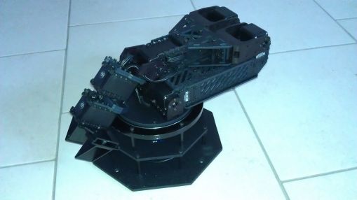
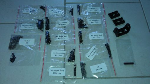
I have a LOT of leftover screws and nuts (for some I did not need even use half of what I had), as well as two F3 brackets that are never used in the assembly guide. I guess that's another little oddity that the normal kits don't have.
Next time, power-up and making it move, from even another city :) Yeah!


