Cut Belts and 3D printed pulleys
By Xevel on Tuesday, February 8 2011, 09:46 - Eurobot 2011 - Permalink
Driving the wheel without ruining the general shape of the Xachikoma leg has proved to be an interesting problem.
Also, remember that I'm not a mechanical engineer, so I may miss some well-known techniques and solutions here and there.
<otaku>
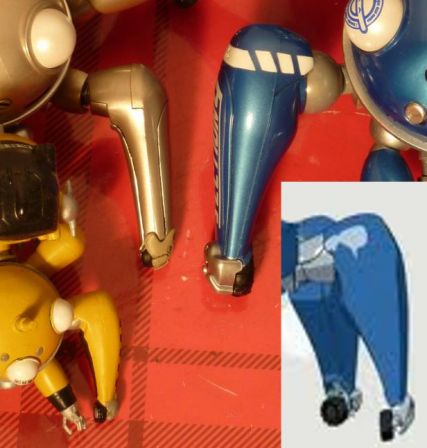
Tachikoma leg shapes are a little different from a source to another, even when you consider sources related to the first season only. Each action figure has its own, and even in the anime it's not extremely consistent between the opening credits, the cell-shaded ones you see during the episodes and the hand-drawn ones in the art-books.
</otaku>
Now back to the robot. The main concerns when designing the tibia were:
- keeping down the leg width around the wheel (for aesthetics and to avoid blowing the max perimeter too quickly)
- closed-loop control of the wheel.
- control precision: little or no backlash, no slipping.
- having a way to tell if the wheel is touching the floor or not
- decent driving speed (30cm/s at least)
- being able to switch from fixed to powered to free wheel.
The last one has been abandoned, due to the complexity it would add. Too bad, the Xachikoma will not be able to actually skate like last year's robot (but it still can fake it ;) ).
First designs had either the wheel directly on the motor or a gear-based transmission, both of which had advantages but were at the time way too large since I wanted to use an optical encoder for control. This led me to consider using another synchronous transmission that allowed more freedom for relative placement of the driving and driven axes: a timing belt. I also came across an off-axis magnetic encoder, that allowed me to reduce width even more.
The size of the magnetic ring for the encoder (32mm diameter) determined the minimum size of the wheel, and from there I chose the Banebot 41mm, 30A shore, as it has very good grip and the tire is fused with the wheel core, so no risk of slipping. Only problems would be the color, and the non-metric grub screw I had to buy an hex key specifically for... why on earth put a non-metric screw on a hub with a metric, 4mm axis?
Now with the size of the wheel determined, I had to start looking for pulleys that could make this mechanism a reality.
Pulley design
First thing I learned when looking at the pulley offer is that I would not find easily what I wanted. Whatever the type and size of timing belt (and there are a lot), impossible to find a pulley that is either less than 20mm wide or reasonably priced (often neither on nor the other). So I chose to make my own, 3D printed.
Choosing the type of belt got down to the question "what kind of pulley teeth are big enough to be accurately 3D printed, and small enough so the ~25mm of diameter pulley would have at least two engaged at any time". My choice went to the HTD 5M specification, since its size is OK (5mm from one tooth to the next), it's availability at various short length is very good and it's a metric belt, not an imperial-unit-based one. The smallest standard width however is 9mm, way too much for me, all the more considering the extremely low torque it would have to transmit. After cutting a few belts to see the smallest width I could reach, I settled for 3mm, to be perfectly sure I keep at least one inextensible thread intact in each belt.
Then I had to design the pulleys themselves. It's surprising to see how little information is available online on timing belt teeth. I had to cross reference various slightly different designs from different manufacturer to get something susceptible of functioning.
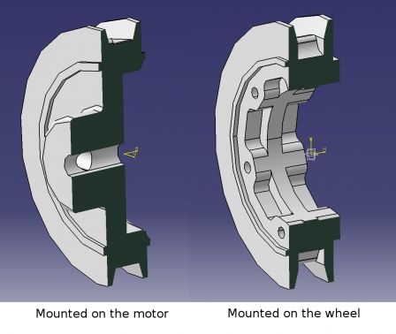
The one mounted on the motor is made so it covers partially the motor, and has a central hub with perpendicular holes for two grub screws. The other does not have a hub, but instead has a hole large enough to let the Banebot wheel hub through, and 6 threaded holes for screwing it to the wheel (only 3 would have been enough but the other are there for backup, if one thread is damaged). This allows for easier assembly and disassembly.
Cutting the belts
To reduce cost, I bought two 15mm wide HTD 5M belt with the idea of using one for tests and cutting the other in 5 pieces, so as to have one spare belt.
My first try was to put a cutter blade on a 3mm spacer, and turn the belt against it... took me some time but the result was nice. Problems: it took half an hour, I nearly cut my finger twice, and blunted the cutter blade completely. The teeth are very hard and trying to cut them like you cut your steak, going back and forth with the blade, tends to take a long time and kill the blade in the process.
Second try, with scissors, was a big failure, with uneven width.
So I made this little one-time-use tool from stuff lying around.
On a base plate, there is a 3mm spacer, on which is bolted a cutter blade. A pole is mounted for the belt to press against. You maintain the belt firmly against the base plate and the pole with the thumb while pulling it with the other hand, and in 30 seconds you have a shiny new 3mm wide belt (actually, the width is more around 3.2mm since the blade has its own thickness... Should have accounted for it when choosing the spacer). Also, no need to change the whole blade each time, just break the tip after two cuts and start again.
Current state
As seen in the previous post, I received the parts not so long ago, including the 3D printed pulleys from i.materialise.
Here is what the whole tibia looks like, still without electronics.
Tests with the belts showed a little too much friction here and there, mainly due to the fact that my cutting technique is not very accurate (width precision is around +/- 0.2mm I would say) and the printing material is a little rough. A solution I'm looking into is to add a little bevel to the side of the belt teeth, and so far it looks promising.
Most of the requirements should be met, at the exception of the powered/free/fixed wheel modes and maybe ground detection. After seeing the amount of tension needed for the belt, I think my initial plan to sense when the wheel touches the ground with a FSR will not work. The sensor seems to be already under too hight pressure compared to what will be added by supporting the weight of the body. Testing will tell, but considering that on these sensors resolution decreases when pressure increases, I'm not very confident :/
P.S : I'm all for open source, but cleaning things up to make them presentable takes time, time that I don't have much of, and time which is lost if nobody cares. If anybody is interested in further details, 3D models, etc, don't hesitate to say it and I'll try to release stuff.


Comments
Impressive stuff man.
T'es devenu un robot la je pense par contre :/