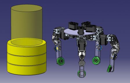
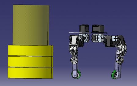
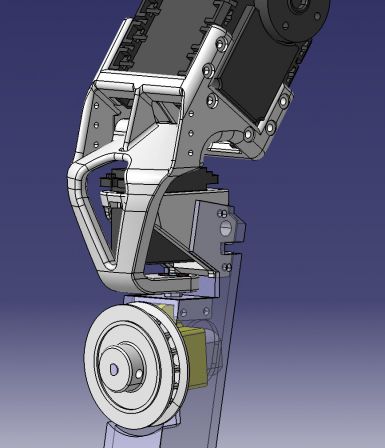
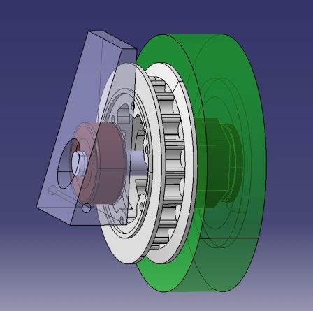
A lot happened since last post, and things are getting very close to their final shape.
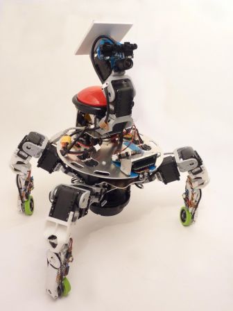
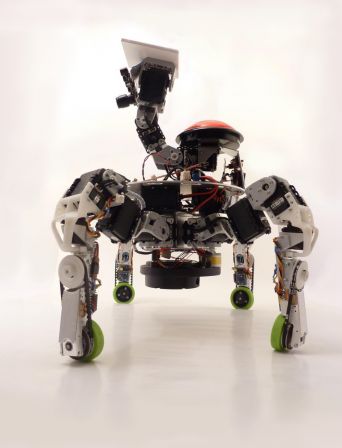
The robot got some brand new 3D printed motor mount (thanks i.materialise!), all the required electronics in the legs, a second camera and a rotating laser distance sensor (the Neato LDS, from the XV-11 vacuum cleaner robot)!
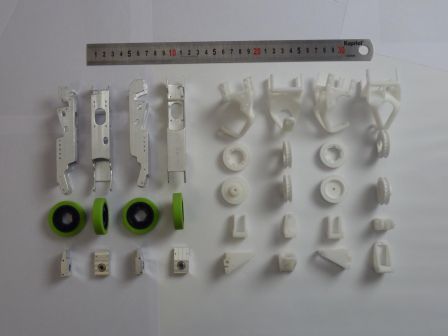
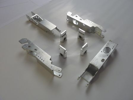
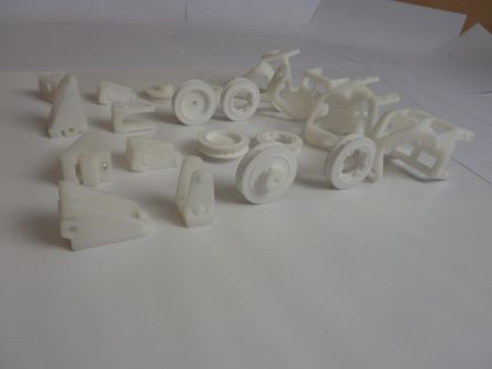
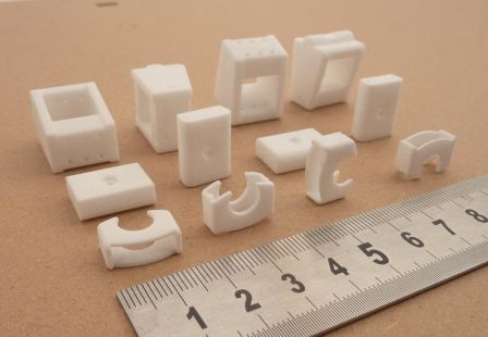
New 3D printed parts
From front to back row: a part used to lock the ball bearing in place, the lower bearing mount and the motor mount,
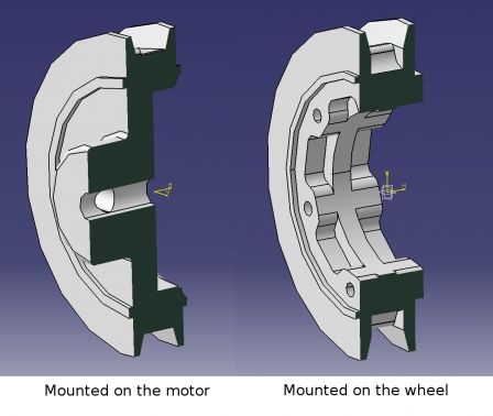
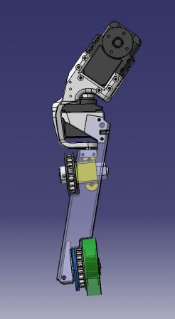
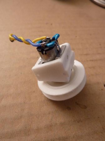
That's what the motor + motor mount + pulley looks like when everything is assembled. This goes inside the aluminum tube.
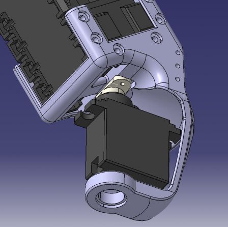
The motor is taken between two layers of 0.25mm aluminum sheet. With this, there is no risk of deformation of the polyamide part, plus it allows for two M2 grub screws (both in the bottom of the part, one close to the front, one close to the back) to secure the motor and reductor in place without blocking the gears.
The motor mount and the part with the ball bearing are now two distinct elements. With the new motor mount design, it was necessary to split the two, as one is fixed and the other has to be adjusted to have the right belt tension.
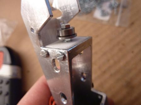
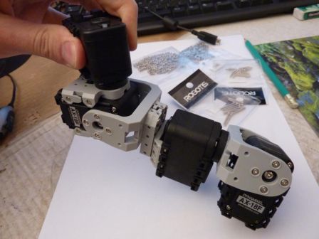
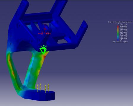
My first thoughts when I designed the mechanism was that little to no effort would apply to move the bearing out of its hole, but torsion in the tibia support part quickly showed that it was not the case.
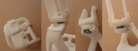
This little part keeps the bearing where it is. Here it's demonstrated with an old motor mount.
Leg Control Board
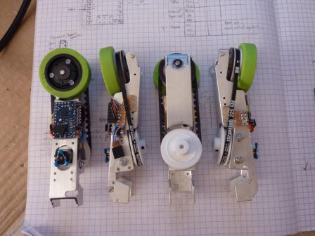
Each leg is fitted with a Baby Orangutan B-328 that controls the motor, the magnetic encoder, the wheel orientation servo, and talks on the Dynamixel Bus as a real Dynamixel device. Right now, it masquerades as an AX-12+ and can communicate with Roboplus :)
In order to have it talking on the Dynamixel bus, I had to apply two important modifications on the B-328 board: change the oscillator to a 16MHz one, and remove the user LED (the red one).
Having a 16MHz oscillator instead of a 20MHz one is needed to join the bus at 1Mbaud. I found the perfect replacement here (Murata CSTCE16M0V53-R0) .
The LED had to go because it's tied to the ATMega328p's UART TX, and caused the idle tension on the line to be as low as 1.8v (using only the inbuilt PD1 pull-up resitor) when it should have been 5v. This does not play nice with the original usb2dynamixel, which often saw 0x00 bytes that were not there. Unsoldering (or... destroying -_-") the led solved the problem.
CMUcam3
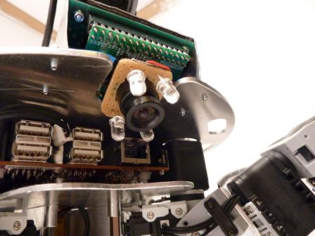
Having a second camera might seem overkill, yet it addresses one of the most important sensory question for this year's competition: "what color is the square In front of me?". It also be used for line-following, and identification of the team's color at startup (one less switch to flip myself... yeah I'm lazy like that ;) ).
I will write a simple custom firmware for it, that will probably do segmentation (it's quite easy in HSV with the colors used on the playing field and playing elements), basic line following, and maybe some rough position tracking based on the grid. The observable area varies with body height and rotations, and the lens distortion is quite important in the corners. Fun times ahead to extract meaningful information ^^.
Owing to last year's disappointment with the light conditions during the approval phases (very different light conditions in different parts of the playing field, hard shadows, yellow lights...), I decided to add some powerful white LEDs on the camera to try to have at least a spot of well-lighted ground...
Neato LDS
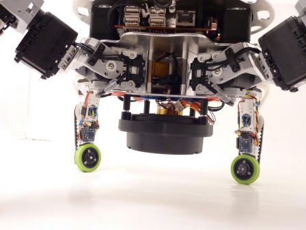
The lidar is mounted upside down, below the body. During normal operation, the sensing plane of the LDS will be around 8 or 9cm above the ground, and it's aim will be to detect obstacles I can't go over (like the opponent :p ).
I'm still working on a protective cage around the sensor to avoid any damage to it. I don't want to know if it can support the full robot weight ;).
As always, a lot more pictures are available in the gallery!
