Design of the Bioloid-based Xachikoma for Eurobot
By Xevel on Sunday, December 12 2010, 22:22 - Eurobot 2011 - Permalink
At first, the Xachikoma project was completely separate from my participation to Eurobot. However, building two complex robots at the same time would have been way too time consuming, and nearly impossible to financially overcome. That's why, as I hinted in previous posts, I chose to merge the two projects into an Eurobot-playing version of the Xachikoma.
Of course, the two projects had different goals: one needed to be able to play by this year's Eurobot rules, whatever its means of achieving it, when the other had to look and act accurately like a Tachikoma... Not exactly a perfect match!
So the idea is this: build a robot which has the possibilities of moving like a Tachikoma (legs with enough degrees of freedom (DOF) and powered wheels), fitted with lots of sensors and equipments to be able to score some points and not be ridiculously unadapted for the competition, all of this without giving too much importance to the cosmetic aspect. This way, I can work on the mechanics, electronics and leg movements this year, and make an accurate-looking Tachikoma later. Also, I don't want to show up at the competition with a robot so unadapted it would have to rely on luck to be accepted past the approval phase. That would be kind of wasting the time of the referees and other participants.
The main structural differences between the original robot and the one I'll make this year are these: the Xachikoma won't have a pod, and probably no arms or eyes either :/ . The body, while still round, will be significantly different from the cute rounded blue shell we are accustomed to. On top of the body will probably be a moving structure destined to maintain the beacon support at exactly the right height and inclination whatever the body movements. On the bottom part of the body, the Neato Piccolo LDS (Laser Distance Sensor, aka the lidar I referred to in previous posts) will be mounted head down, but this still needs some consideration...
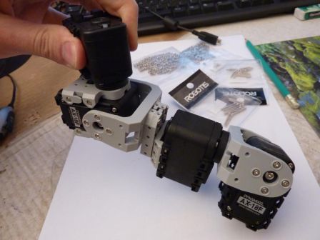
The chassis of the robot is heavily based on the Bioloid Premium Kit I talked about earlier. This is the core of the robot: 16 AX-12+ (at least 4 of which will be replaced by AX-18F), plus custom parts for the body itself and the tibia. With the AX-12+ and even more powerful AX-18F, the robot will be able to easily bear the payload (Beagleboard-xM, Neato LDS, PSEye camera, controllers, batteries, dynamically stabilized beacon support, other sensors...).
For size comparison, here is the chassis (I just began the 3D model of the body) next to a tower of playing elements. The perimeter when standing like that is a little below the 120cm mark, and it can easily be shrunk or widened by changing the leg's position.
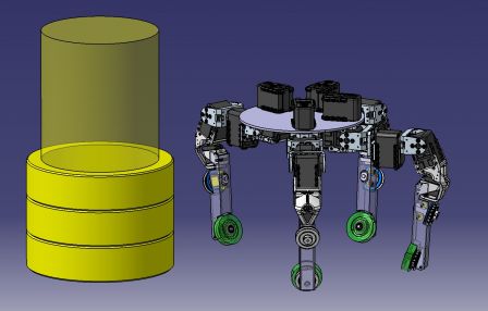
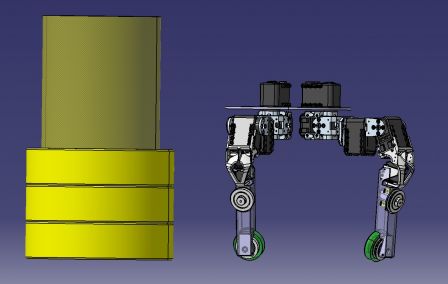
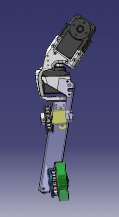
The leg has two parts: the first one is fully built from the Bioloid Premium Kit elements, and goes from the body to the knee. It is composed of 4 Dynamixel servos, arranged to have kinematics identical to the Xachikoma prototype, and to the Tachikoma. Particularly, the axes of the first three servos are concurrent, and the axes of the last two as well.
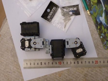
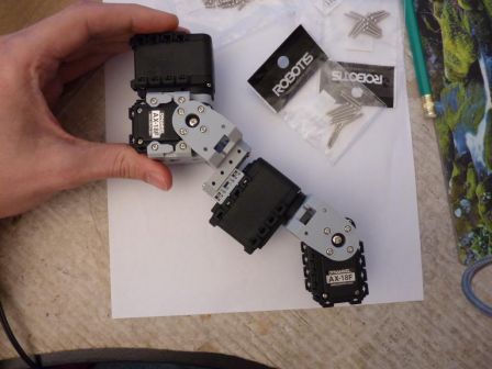
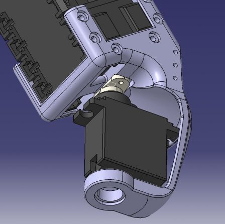
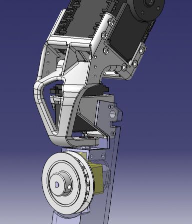
The second part of the leg is custom made, and goes from the knee to the wheel. It's composed of (from top to bottom): a servo support (weird shaped white piece, 3D printed), a metal-geared digital micro-servo, a second servo support (second white part, 3D printed), the tibia cut out of a 20x20 aluminum tube, a motor with its bracket (yellow part), two pulleys(also 3D printed) and their timing belt (not shown), and a wheel. Add to this a force sensor to know when the leg is on the ground, a magnetic encoder for motor control, probably one or more contact or proximity sensors, and a Baby Orangutan to manage all of this.
The wheels are nice and have good traction. Only problem could be the color (green!) ^^. The rotation axis of the small servo passes through the contact point of the wheel with the ground, which has the advantage of not affecting too much the kinematics of the rest of the leg.
The servo supports are tricky parts: they must allow for +/- 90° rotation of the lower part of the leg, and yet be able to support all the weight of the robot, even with occasional shock. And on top of that, as it's the outermost part of the leg, it has to be as small as possible to avoid breaking the perimeter limit. It also mustn't get in the way of the tibia movement by reducing the range of the other servos of the leg. All these consideration led to this (arguably efficient) design.
They will be printed in ABS plastic by the cool guys at i.materialise. ABS is a strong and rigid material, with a is very dimensionally stable and accurate printing process (meaning the part has little risk of being deformed while printed). Using Finite Element Analysis, the profile of the part has been refined to remove as much as possible the weak points of the design. Here is what I got on one of these tests:
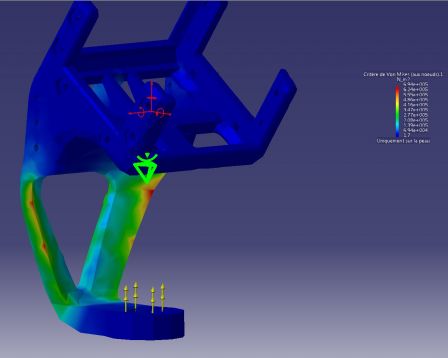 As you can see, the stress is spread across the whole lower part, with two potential small weak spots (in red). The first iterations had just one big crimson area at the bottom of the part, so this is an improvement ^^.
Have a look here for an interesting tutorial about FEA.
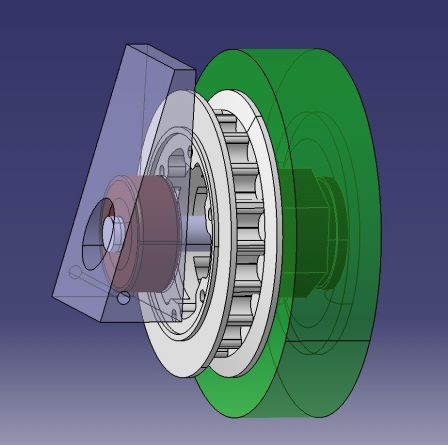
The pulleys are more of a bet. I wanted a way to drive the wheel without slipping, yet I did not have enough space to fit gears, or commercially available timing belt pulleys... so I will try to print them with white polyamide (called "white, strong and flexible" by Shapeways).
The belt will be a 225 5M HTD (225mm length, 5mm between two teeth, High Torque Drive), but with non conventional width. I will try to reduce it to around 3mm, instead of 9. This would allow for pulleys to be way smaller (7mm width instead of the commercially available 20mm). I redesigned the pulleys from what I could find about the 5M HTD specification (ie. not much), and took this chance to make them just the way I need to mount on my mechanism. For example, I added a small ring on the side of the pulley that will allow perfect centering of the multi-pole magnetic ring that goes with the magnetic encoder (the blue ring). The pulley on the wheel will be mounted with six nylon screws onto the wheel, while the one going on the motor will fit on its shaft with a M3 grub screw.
Quite a few details are still in the design phase (like the body... a big detail!) but this is all I can show right now :)
In the next few weeks I should finalize this design, have the plastic parts printed, the aluminum part CNCed and the other parts shipped or hand-made. To be continued !


Comments
Be carefull with this advice from the rules :
Attention : Si le robot fait moins de 18 cm de diamètre ou est totalement transparent, il pourra être confondu avec un roi ou une reine par le robot adverse
Yep, I'm aware of that. Around the legs, it will be larger (around 23 to 28cm wide) but this won't be the case above them. I just won't complain if the opponent's detection is based on this and he does not see me.
Or lift you up, like a pawn :D